Time to read: 6 min
AI tools are evolving quickly, and they’ve already proven incredibly useful across nearly every industry. But in mechanical engineering, precision and accuracy matter, and there are still some technical details that AI has trouble getting right. As many of us are trying to keep up with the latest tools and learn the best ways to use them, it’s important to understand how they can help with certain tasks, but also their limitations.

In this article, I’ll highlight a few examples of “AI fails”, including prompts and iterations:
- Stress Strain Curves
- CAD
- Technical diagrams
AI for Stress-Strain Curve Diagrams
AI models can generate charts, but they often lack engineering-grade accuracy, especially without proper prompting.
For example, I asked for a diagram comparing the stress-strain curves of stainless steel, aluminum, polycarbonate, and TPU. What I got was “close” in terms of possible yield points and lines that looked different enough to represent different materials, but the rest was inaccurate, and the curve for TPU was a flat line at zero.
This is a problem because in engineering, the details matter. Stress-strain curves aren’t just pretty pictures—they determine how to design for stiffness, safety factors, deformation limits, and failure modes. A misplaced point on a curve could be the difference between a safe design and a catastrophic failure.

Prompt: Please create a diagram comparing stress-strain curves of stainless steel, aluminum, polycarbonate, and TPU.
Of course, there is not exactly a “correct” answer for this, because the chart would be based on empirical data and determined by other factors, such as material grade and temperature.
For the next iteration, I included a data sheet for a specific polycarbonate material, but the result was still far from what you would expect.

Next, I specified environmental details, using 50% humidity and 20 degrees Celsius, and prompted the chat to show a more realistic curve. The results are better, but the plot is more linear, based on the data points that were used. There was no curve as the plot entered the plastic region after the yield point, as is to be expected.

For reference, here is what a typical stress-strain curve looks like:

Lesson: You can sometimes get the minimum results you need from AI-generated diagrams with edits and annotations, but the cleanup can take as much effort as drawing them from scratch.
AI for (Text-to) CAD
Prompting AI to generate CAD models seems ideal in theory—just describe your part and let the machine build it. However, in reality, most AI-generated CAD outputs are either geometrically invalid, lacking key features, or missing parametric constraints.
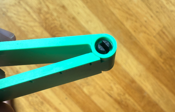
Let’s take a look at my prompt below, where I tried to create my multi-tool phone stand from the FictivMade project.


Here is an image of my design that I was trying to recreate. I tried using the actual image as part of the prompt on a second try, but it didn’t help the results much.

I also tried a prompt for another concept, using the idea of gears from the Text-to-CAD site.

We got a sphere with a gear on it, but not a spherical gear.
With many of these tools, the quality of the output largely depends on the amount of detail you provide. Of course, with a better prompt, this might come closer to something usable, but do you really want to spend all day entering prompts, only to have the results still fall short?
I also tried Onshape’s API (Developer Portal). It’s capable of taking code and prompts to create simple objects—for instance, a 5 mm sphere and a 3 mm cube. However, with more complex tasks like a phone stand, it also struggled with prompting alone.
There are already many AI tools for 2D drawings, which can be a significant pain point for mechanical engineers. The Fictiv platform accepts 2D drawings, but also works to optimize and match your project requirements to alleviate documentation updates.
Lesson: CAD is not just shapes—it’s dimensions, tolerances, and intent. Until AI understands design intent, it’s more of a toy than a tool for serious CAD.
AI for Technical Diagrams
Next, I prompted ChatGPT to create a diagram showing weld joint types, including butt joint, corner joint, edge joint, and T-joint.

At first glance, this looks pretty close, but let’s compare it to an accurate diagram below. Notice that a butt joint typically has the ends touching. The edge joint above does not have the ends flush, and the corner and Tee joint don’t show the sheets as separate parts. It’s possible to make these tweaks, but it takes more time and effort than is necessary.

For another test, I asked AI if a polycarbonate part with a step from 3 mm thickness to 2 mm thickness would have sink in the thicker section. Its response was thoughtful and useful, even recommending tapering or blending the transition. However, when I asked it to display an image of how the part could be blended out, it had difficulty conveying this in a simple image, as shown below.

I figured I would give Gemini a try next, since it actually does a pretty good job generating some images. Below is the result, which has some inaccuracies.

Note that you can edit and highlight areas to change on the image or chart, but it’s not always as easy as it sounds. These may be “small” visual errors, but in technical communication, small errors can mislead engineers, fabricators, or students. Fixing the AI output often takes more time than drawing the diagram correctly in the first place. See the correct diagram below, also featured in our sheet metal welding design guide.
Lesson: Accuracy beats aesthetics every time in engineering diagrams.
10 More Ways AI Can Fail at Mechanical Engineering
- Tolerance Stack-ups & Fits
AI often ignores GD&T and fit standards (like ISO H7/g6), leading to assemblies that are either too loose or impossible to assemble. - Material Selection
It may suggest materials for one property (like corrosion resistance) while overlooking weldability, machinability, fatigue strength, or cost that you may not have specified. - Fatigue and Creep
AI tends to focus on static strength and misses long-term issues like fatigue cracking or creep at high temperatures or in strenuous environments. - CFD and FEA Oversimplification
Simulations generated by AI may have bad boundary conditions, coarse meshes, or misinterpreted stress results, giving a false sense of safety. - Standards and Codes
Engineering designs must comply with standards such as ASME, ISO, and API, which AI may not apply correctly, risking unsafe or even illegal designs. - Manufacturing Process Knowledge
AI can design shapes that appear feasible but are difficult or impossible to manufacture, such as designs with undercuts in molded parts or internal radii too small for CNC cutters. - Thermal & Environmental Conditions
Unless specified, AI may assume a specific ambient temperature and ignore factors like UV degradation, cryogenic brittleness, or high-temperature creep. - Nonlinear Material Behavior
AI usually assumes linear elasticity, missing hyperelasticity in rubbers, viscoelasticity in plastics, or strain hardening in metals. - Safety Margins
It can output “exact” stress numbers but forget to include factors of safety, leaving designs on the edge of failure. - Units & Conversions
One of the most dangerous mistakes: AI sometimes confuses units (psi vs. MPa, N·m vs. kgf·m), resulting in errors that are off by factors of 10 or more.

Conclusion: Will AI Replace Mechanical Engineering?
AI is an incredible assistant, but in mechanical engineering, precision is everything. AI falls short when accuracy, intent, or real-world integrity matter more than surface-level plausibility. When using AI as a tool, it’s essential to include as much technical detail as possible in prompts and iterations, while also understanding its limitations.
For now, think of AI as a brainstorming partner, not a replacement for careful engineering judgment. It can speed up drafting, inspire designs, and provide quick reminders, but the real work of engineering still depends on human oversight.
That being said, AI tools can still be helpful in product design and manufacturing. Fictiv integrates AI into our platform, providing material selection advice, and increasing efficiency for your orders. We also use human engineering teams on the ground to see your parts through to perfection.