Time to read: 7 min
We spent several weeks working with Mindtribe to build a $500 electric car to race at the Power Racing Series at Maker Faire, using the base of a Power Wheels Lambo.
The Power Racing Series is this amazing event where adults-who-still-want-to-be-kids dress up in crazy outfits and race their souped-up Power Wheels cars for moxie points and maker-style glory.
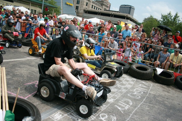
It was our first year entering the race, so we decided to document our process, in the hopes that more people will be inspired to build new and crazy cars to compete in future races, or just for fun.
In this post, I’ll dive into how we approached the build, how we sourced our components (including the tools we used to calculate vehicle acceleration and velocity + required battery capacity for the motor), and how we overcame some critical challenges along the way.
Finding the Frame
Since we were running on a very tight timeline for this build, we decided to just buy an already assembled go-kart and retrofit as needed, rather than build a new frame and individually add on each component.
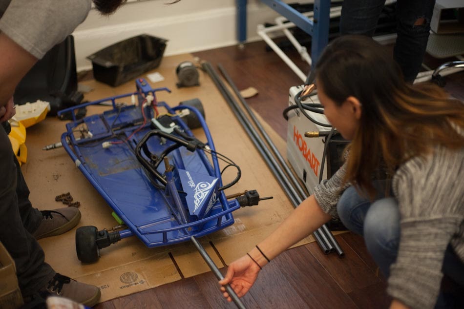
After a few hours of research I settled on the Razor Ground Force Drifter: A tiny children’s electric go-kart. I went to meet the owner at his home and after a bit of haggling, walked away with an assembled kart for only $100 bucks.
I brought it back to the office and placed the Lamborghini body over the frame, and it fit like a glove—the plan was coming together perfectly! I should have known then that this was too easy…
Sourcing Components
What we realized almost immediately about our seemingly perfect go-kart was that Razor decided (for some crazy reason) to avoid standard sizes for their components. That meant our plan to swap out parts (e.g., rear axle, steering rods, sprockets, etc.) for items we could find at a local scooter store or on eBay wasn’t going to be possible.
Furthermore, Razor chose not to standardize components between the same family of go-karts, meaning parts that fit a Razor Dune Buggy kart wouldn’t fit our Razor Ground Force Drifter kart. This put serious holes in our original plan to swap components until we had the kart we needed.
Divide and Conquer: Breaking into Teams
To move forward, we divided into teams that could each attack the build from a component level, to ensure we were ordering the right equipment.
Team 1: Drivetrain
Responsible for selecting the motor, connecting it to the drive axle, and getting the best blend of acceleration and top speed out of our vehicle.
The drivetrain team sets the groundwork for the rest of the build, so it was important that they did the proper calculations up front to select the right motor, which would impact weight distribution and turning radius for the steering team, as well as the type of batteries and stopping power required for the breaking and powertrain team.
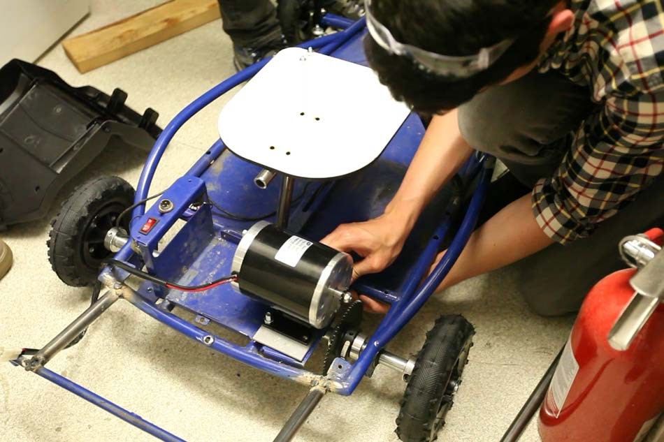
After plugging and playing with several numbers, we found that an 800-watt DC motor with a 1000-watt motor controller would best suit our needs. Also, because we valued acceleration over top-speed, we decided that we would need more torque than what the current 1:3 motor sprocket to axle sprocket ratio provided.
We went from a 32 tooth axle sprocket to a 60 tooth sprocket, adjusting our ratio from 1:3 to 1:5.5, theoretically increasing torque from 8Nm to 15Nm.
The issue we ran into here is that Razor uses an odd 19.85 mm rear axle, and no one makes roller chain sprockets over 20 teeth with a 20mm bore size. We decided, in the end, to buy a 60 tooth roller chain sprocket with a ¾” bore diameter and use a 20mm drill bit to increase the opening.
Unfortunately, this led to another problem: Now that we had opened up the bore size, the original key that locked the sprocket in place on the rear axle was too large, so we spent some time milling it down to the right size.
But then…the sprocket bore opening was just slightly larger than the axle, which was causing some wobble of the rear sprocket. We fixed this issue by using a thin shim to center the sprocket and then clamped it on both ends with shaft collars. Not ideal ,since this was additional unsprung weight, but we decided it was our best option.
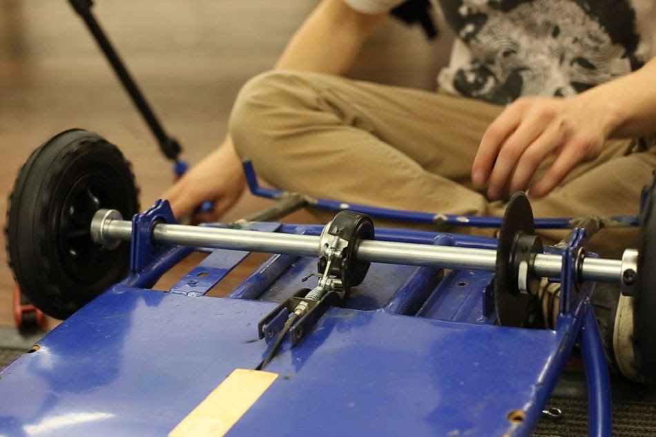
Once the sprocket was installed, the motor installation was fairly straight forward. We welded a steel plate to the frame to mount the motor, which was then lined up and held down with 4 bolts. We used washers to raise the motor and act as a tensioner on the chain.
Team 2: Braking + Powertrain
Supply power to the motor, motor controller, throttle, kill switch, and most importantly, stop the vehicle.
With the motor chosen, it was up to the Braking and Powertrain team to figure out how we were going to provide power to the motor, and on the other end, kill power and bring the car to a stop.
We found that for the 36 volt motor, we would run 3-12 volt batteries in series and made sure that the batteries we selected would give us at least the 22 Ah we required for the motor.
At this point, the bigger issue became weight. While we wanted to use a lighter battery, we were burning through our $500 budget faster than expected and had to settle for cheap Lead Acid batteries which weighed about 20 pounds each!
Pro Tip: Don’t make batteries an afterthought! They add some serious weight and complexities if you don’t plan accordingly. For next year’s race, we will definitely be improving our battery setup.
With all the added weight and focus on acceleration and top speed, we realized we wouldn’t need to adjust the braking system in the end. Though the kart was using cheap belt brakes, our top speed is only about 12 MPH, which doesn’t warrant an entire cycle to build a better braking system.
Team 3: Steering
Design the car for best possible turning radius, weight distribution, wheels, and driver posture.
And lastly, our achilles heel: Steering. This was an issue we anticipated from the start of the build: The issue here was that we had no rear differential, meaning that both rear wheels were going to move at the exact same speed, even through turns. This is very bad for turning radius.
Traditionally, vehicles have some way of implementing a differential, which allows the outside wheel to spin faster than the inside wheel when taking a turn. The consequence of not doing this is that as you turn, the car wants to keep moving straight forward and makes it nearly impossible to maintain speed coming out of a turn.
We figured we could limit the impact of not having a differential by choose the right tires and trying to drift through the corners. But yet again, Razor unfortunately uses unique sizes for all their components, so finding wheels that fit on our rear axle and front tire rods was nearly impossible.
We ended up having to settle for thin, 8” diameter wheels that typically fit the Razor Dune Buggy and while they were close, they still needed some “adjusting” to get them to fit. The new rear wheels were just slightly too large, so we used thin aluminum sheets to create round shims that fit around the shaft to close the gap. This was okay on the rear end because the wheels did not spin freely and actually rotated with the axle.
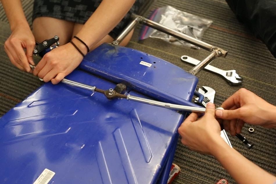
For the front wheels, it was a little more tricky. The new wheels didn’t fit the existing tie rods, so we needed to use the tie rods that came with these wheels. All seemed great until we realized that the new tie rods had a longer leverage point than the old ones, so our original non-adjustable steering rods wouldn’t fit.
We ordered some adjustable steering rods and installed them only to realize that the connection point on the new steering rods and the old steering column now don’t align.
At this point we were running up against our budget and couldn’t spend anymore, so we all huddled together, grabbed a vice, and ever so slightly bent the steering rods until they fit perfectly. Sometimes a hack is all you need!
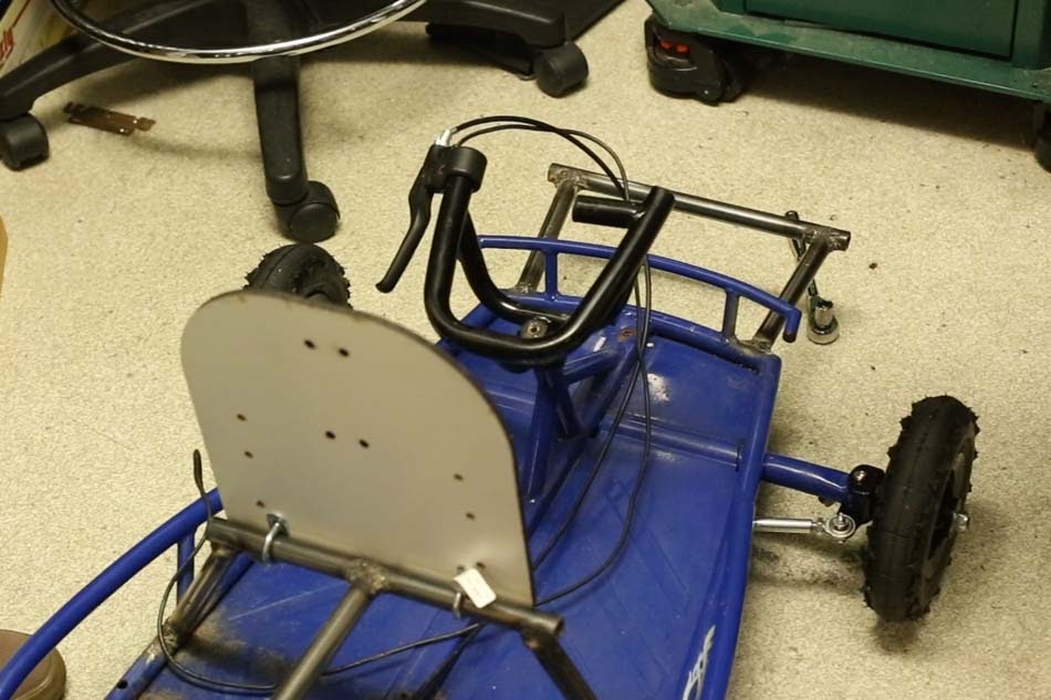
With steering in place, it was time to install the seat. We had previously already welded a seat frame on the car so that we could sneak the batteries below the driver. We knew the seat had to hinge up and down, so we used some U-clamps to hold the seat down and also allow it to rotate over the front support bar.
Final Tune Ups + Testing
With a motor installed, the steering working, and the seat functioning and ready for the batteries to slide in, we took the last few days before the race to get the wiring and power to the motor done ,with just enough time left to take the car for a few test laps.
In hindsight, we probably should have left more time than we did to complete the build—the end was a bit of a frenzy to get everything done.
In Part 3 of this series, we give you a look at the final car in action at Maker Faire!


