Time to read: 6 min
Before the invention of CNC (Computer Numerical Control), machinists relied solely on 2D engineering drawings to determine machining steps and parameters. Manufacturing has come a long way since then, thanks to precise 3D modeling and CAM (Computer Aided Manufacturing) programs.
In 2022, we’re fortunate to be able to import solid 3D models into a CNC machining program — such programs automate the machining steps and parameters needed to produce the desired component. However, even with these technological advancements, drawings are still necessary to define tight tolerances on critical features and other special requirements. And learning to optimize drawings for CNC machining is a critical engineering skill.
In this article, we will share techniques to ensure your drawing is comprehensive for any manufacturing process and can be easily understood by manufacturing personnel. For our purposes we’ve used SOLIDWORKS, but the process can be easily replicated using other engineering drawing software.
Let’s get into it!
1. Open the Drawing File and Insert Drawing Views
First, download and open this Solidworks drawing file to use as a base for creating your CNC drawing.
Next, we need to lay out the drawing views, which are commonly referred to as orthographic projections, or 2D view/drawings to represent a 3D object. The number of drawing views required for a given component depends upon the part geometry. Simple parts can be fully represented with two or three views, while more complex parts tend to need more. We have provided an example solid model of a demo housing part for the purposes of this tutorial.
Our engineering drawing requires three views and a section view, which shows the part as if it were cut in half to view its internal features. You can add drawing views to the base drawing template by clicking ‘Model View’ in the ‘View Layout’ tab and selecting your model (see detailed instructions from the SOLIDWORKS website here).
Pro-tip: For most CNC machining drawings, two or three orthographic views are sufficient to describe the geometry, dimensioning, and tolerancing of the component to be machined.
Setting Up Drawing Scaling and Views
It’s also important to scale drawing views properly so you have enough space for notes, dimensions, and mechanical drawing symbols around each view — it’s difficult (and annoying) to resize the views after the dimensions have been placed.
SOLIDWORKS automatically adds center marks to the holes, so if your software doesn’t, add them. Doing so is a convention for showing the manufacturer or anyone reading the drawing where the holes are. Most software has simple-to-use engineering tools that can place centerlines, resize views, and perform other functions. It’s a good idea to add construction lines in all views to show centerlines, center marks, and center mark patterns.
Reference views or cross-sectional views (such as Section A-A below) are another element to add for the manufacturer’s benefit, because an isometric view or two can help them better understand what they’re fabricating. Generally, you want to add enough views to fully define the geometry, dimensioning, and tolerancing of the component to be machined.

2. Geometric Dimensioning and Tolerancing (GD&T)
Pro-tip: this tutorial provides some GD&T basics. For a more comprehensive guide to GD&T, including a library of GD&T symbols, check out this website.
Dimensioning
The first step of the GD&T process is dimensioning the orthographic views you added to the drawing. This process is significantly simpler now that most of the geometric information is contained in your solid model. Start with the overall dimensions, the ones which determine how much raw material will be needed to machine your component.
Next, define the critical part dimensions. Critical dimensions are those that must be accurate, usually because they’re where the part interfaces with another part. Hole patterns are a good example of critical dimensions — for instance, on the outer four corners of the demo housing part. This hole pattern represents how the part will be mounted to a base and must match the holes in the interfacing part.
Tolerancing
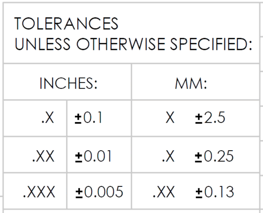
Prior to tolerancing an engineering drawing, consider two things: the tolerance you want and the tolerance you’re calling out — and bear in mind that generally, tighter tolerances increase the cost of a CNC machined part. Next, refer to the general tolerance instructions in the title block of the Fictiv drawing template.
The tolerance is determined by significant digits of the basic dimension, as shown in the table below.

Now, let’s say the desired distance between the outer holes is designed to be 114.3 mm. If you call out the dimension as “114”, general tolerance per the above table would define the tolerance to be (X) at a value of ± 2.5 mm. Calculating the range for the “114” dimension, based off the X tolerance, the acceptable distance between the holes is anywhere from 116.5 to 111.5 mm. This wide of a range probably won’t work if we are interfacing with another part.
Instead we want a tight tolerance on this dimension, so we’ll use the one-decimal place dimension (.X), which is ± 0.25 mm. Similarly, we’ll use the one decimal place dimension for the inner hole pattern. Also, notice how identical dimensions don’t need to be called out, but simply need a “2X” placed in front of the called-out dimension.
Pro-tip: Geometric relationships and datum lines should also be defined on the drawing, and while we don’t discuss them here, you can read about datums in this article.
For this particular part, there’s a looser tolerance for the height because there are no requirements for how large it can be. So, we can add the dimension to center view with no decimal places, giving us a tolerance of ± 2.5mm.
On the bottom view, I’ve called out wall thickness to be 6.35 followed by “TYP”, which means typical. Essentially, this means that all similar wall thicknesses can be called out with just one dimension to make the drawing cleaner.
Pro-tip: Use all CAPS on your drawing makes it easier to read and understand.

Special Dimensioning and Tolerancing for Holes
After dimensioning the hole positions and other critical dimensions, we need to dimension the hole diameters, depths, and associated tolerances along with any thread tapping required — the top of our demo housing needs four countersunk outer holes and four inner #6-32 threaded holes.
Pro-tip: If you only have threaded holes to call out, you can skip the drawing and simply use Fictiv’s Auto Thread Detection tool.
Identical holes can be called out collectively by placing a “4X” in front of the called-out dimension. In our example, we’re using UNC threads because the taps and hardware are generally more available in the U.S. Also, there are two types of holes: thru holes that go entirely through the part and blind holes that have a specified depth called out with a ↧ engineering drawing symbol. The depth of countersunk holes is similarly called out using a ⌴ symbol.

3. Surface Notes
Drawings are also useful to notify your manufacturer about specific surface instructions. Surface finish corresponds to the type of endmill and the speed that the CNC operator uses to cut the particular surface. In general, 64RMS is a smooth finish, but you may be able to slightly feel the toolpaths. I recommend 32RMS or lower for O-ring interface surfaces and any surface that you want to be really smooth.

Surface finish comparator showing the difference in a few surface finishes.
As with other tolerancing, the tighter the tolerance (and the smoother the surface finish), the more expensive the machining. I’ve added a 64RMS finish to our example title block, but I’ll add a note because we want a smoother finish on the top surface of the demo housing.

4. Manufacturing Notes
The upper left corner of a drawing is used for additional notes for the manufacturer, which may include finishing instructions or part marking. This is the final element to create a clear engineering drawing. In our drawing, we’ll add a note for breaking all edges, as well as a few other useful basic notes:
- Defining units
- Providing tolerance information
- Cross-referencing to solid model
- Brak sharp edges
- Surface finish requirements
- Cleanliness requirements
While not all of the listed notes must be included in every drawing, they provide a good starting framework.

5. Export as PDF
Congratulations! We’ve now finished our CNC machining drawing, and our final step is to export the drawing as a PDF. In SOLIDWORKS, this is as easy as going to File → Save As and selecting PDF as the “Save As Type”. Now you can easily share your PDF and get your part made!Do you need tight tolerance CNC parts? Fictiv is your operating system for custom mechanical parts, and we accept technical drawings and feature-specific tolerance requirements in a range of file formats. We can machine tolerances as tight as +/- 0.0002 and can provide finishing, hardware installation, and quality inspection services, too. Learn more about our full CNC machining services, and create your free account to get an instant quote and free DFM feedback on your designs today!


