Time to read: 11 min
Have you recently assembled Ikea furniture? If so, I apologize. I send my condolences for the frustration you experienced when the holes did not line up with the pins you put in other holes or when you realized you were missing a fastener. The good news is that you did gain something from the experience (other than a piece of Swedish furniture that you may or may not be able to ever move) – you gained excellent experience with slip fit geometry and even interference fit geometry (depending on the machined size of the hole diameter for each dowel pin fit – ha)! Yay!
Pro-tip: If you are looking for a bit of comedic relief to add to your workday, head over to this video where you can see lots and lots of dowel pin slip and interference fits in action with an Ikea furniture assembly that is sure to bring tears of laughter to your eyes!

We’ve previously explored interference fits (press fits), using a dowel pin as an example, to explore interference fit design limitations. Using the example of dowel pins, there is another important application: slip fits (aka push fits or clearance fits). While interference fits create tight assembly tolerances, slip fits are just the opposite—they can easily give you a self-locating assembly, making manufacturing easier when needing close alignment. Want to know more about slip fit geometry and slip fit tolerances? Read on!
Slip Fit Basics
To make a slip fit work, the parts must be able to slip into place, meaning there must be minimal assembly friction. The goal of a slip fit is easy alignment, requiring enough space around the dowel that alignment is easier: no excessively tight fits – this concept is commonly known as slip fit clearance. How much clearance is excessive? More on that in a moment, but first, the ideal uses of slip fits.
Ideal Use of Slip Fit Geometry
A rule of design for assembly (DFA) is to avoid tight tolerances, where possible. If slip fits are only for aligning tight geometry, should we redesign the parts for looser tolerances?
Yes and no.
Sometimes, especially in machinery design, you can’t have the loose tolerances which would be ideal; because, for example, a head bolting onto an engine block needs to be exactly positioned. Dowel pins are perfect for this type of fit: they hold the two parts in correct alignment, allowing relaxed tolerances around bolt location and hole diameter.
Another handy application for dowel pins is when parts need to be disassembled and reassembled numerous times while retaining alignment. While this is rare in consumer products, it’s common in the tools used for assembling them. Assembly jigs—tools for holding parts in correct alignment during assembly operations—are one of the biggest areas that can benefit from slip fit dowels. Another type of jig is a true position fixture, which utilizes a slip fit to determine CNC machining accuracy.
We are going to get into the question of how tight is too tight, but first, let’s discuss how we’ll be communicating those values.
Let Go of Traditional Tolerancing
Tolerancing is simple, right? Draw a line, mark a dimension, give a reasonable range of acceptability, and bam! You’re done. Right? Wrong.
In school, we learned linear tolerances, and good students even paid attention when the professor taught tolerance analysis. But typical tolerancing has a flaw when tolerances get really tight, as they are when using dowel pins for alignment: the square.
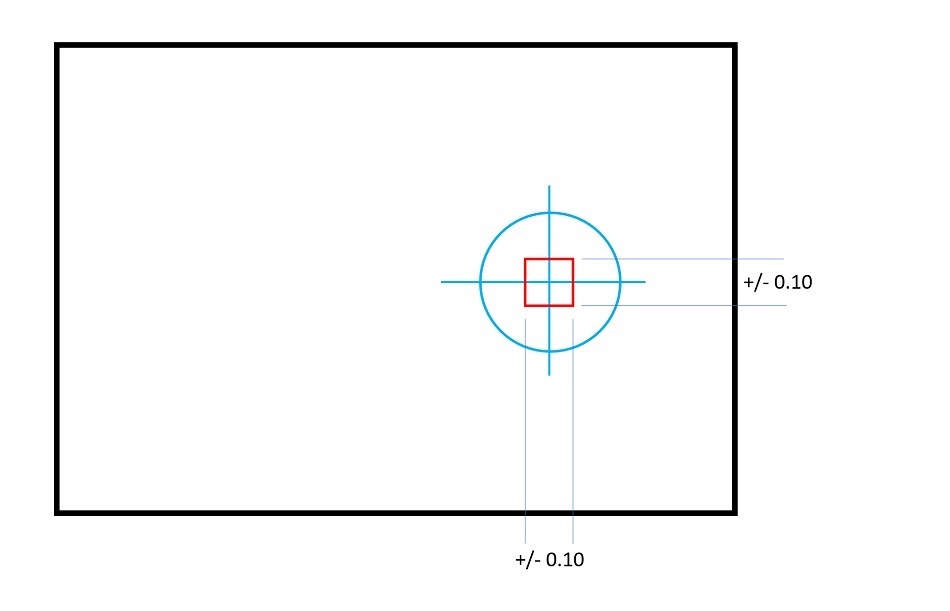
“The square”? For a hole with horizontal and vertical tolerances of +/-0.010 inches, how far off-center can the hole be? Intuition replies just 0.010 inches, but that’s not for the corners—we create a square of acceptable locations, and in the corners, the hole can be 0.014 inches off-center.
That extra 0.004 seems small, but remember, we’re using dowel pins because the parts need close alignment. So, what is the solution to our square problem?
Access our Tolerance Analysis Calculator
That’s not the only issue, right? What if the pin is centered, but not vertical? What if the hole is off-center, off-vertical, and out of round? How much variation is okay? And will they serve ice cream at the banquet? (Maybe that’s only my concern. But it is a big question.)
Slip Fits and GD&T
The gold standard for tolerancing, GD&T (geometric dimensioning and tolerancing), fully resolves these issues, by calling out exactly the acceptable variation in all aspects of design geometry. While they look like a complex symbolic language, GD&T callouts are well worth the time spent learning, and a few basics will illustrate their necessity in slip-fit tolerance for pins.
GD&T uses basic tolerancing for all its dimensions, meaning it looks at the geometry and describes the ideal state. But instead of introducing randomized error (as in the case of the square tolerancing area), each geometric feature is called out with its own set of acceptable tolerances.
For example, let’s look at a simple block with holes for two dowel pins, which will align this block on a flat plate. For this assembly, we care that the block is perpendicular to the plate and is located precisely. We need to translate these design considerations into the corresponding slip fit clearances and therefore slip fit tolerances.
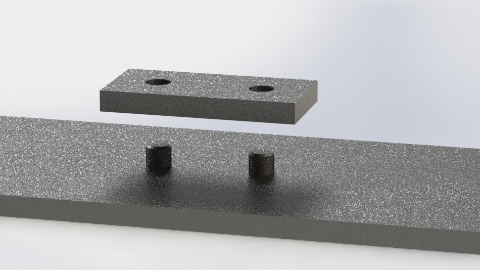
To begin with, we mark out the ideal geometry—due to manufacturing tolerances, the part will never be ideal or 100% precise, but these are the starting points—and then we look at how much variation we can tolerate in each of the features of the block. (“Features,” in this case, means the two holes, but essentially refers to any geometry capable of variation: holes, channels, surfaces, etc.)
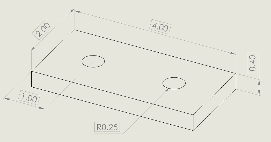
Looking at the first hole, we need to specify several things: hole location variation, cylindricity or hole surface variation, and how perpendicular it must be. But variation compared to what? The bottom? The other hole? Some ethereal fixed point in space? Compared to datums.
Datums are your design’s anchors, and they’re the reason why GD&T is so practical. For our first hole, we care that it’s perpendicular to the bottom of the block (which will rest on the plate), so we mark the bottom of the block as datum A and mark the hole perpendicularity tolerance to datum A.
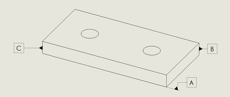
Our second concern is the location of the hole (compared to the front and side of the block, which become our datum B and datum C), which is marked using true position (not to be confused with the Schwarzenegger thriller True Lies, a title that’s an oxymoron all on it’s own). True position solves our square problem by giving us a radius of acceptable variation for the hole location.
Finally, we care about the first hole slipping over a dowel pin (slip tolerance), so it must be fairly cylindrical, and we mark the acceptable variation using cylindricity, so our first tolerance callout looks like the picture below.
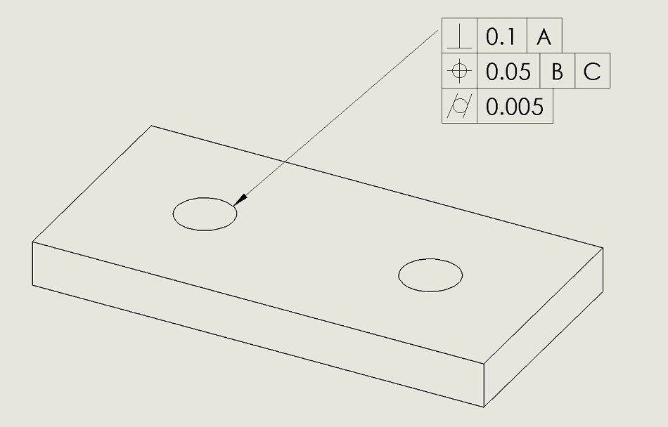
Whew! I’m glad we’re done with that. But, wait! What about the second pin? Here’s where GD&T becomes even more useful.
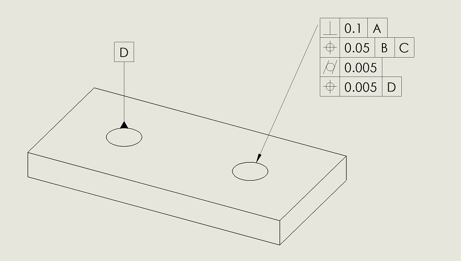
Because the two pins are used for alignment, we know that they will have tight tolerances, so the two pins must align with each other even more than the other features. We can mark the hole for the second pin in reference to the bottom, front, and side surfaces, just as with the first hole.
But once the geometry is marked like this, we also add another callout referencing the first hole. The first hole becomes another datum, D, and we add a second position tolerance, much tighter, which calls out the variation between the holes. And, voila! Without compromising our fit, our manufacturing team has as much tolerance as possible for the geometry that will define the slip fit clearance.
Further Notes on Geometry
And, finally, we can discuss the original topic: How tight should a slip fit be? That’s the easiest part of the whole design process.
To be a true slip fit, the only requirement is that friction not keep the dowel from sliding into the hole. Ideally, that means that the dowel and the hole could be the same diameter. However, in reality, dowel pins are commonly up to 0.0002 inches oversized, which becomes an absolute minimum oversize to ensure a clearance hole (slip fit).
Beyond that, you should allow maximum manufacturing variation. As in the example above, this requires looking at part alignment and specifying tolerances referencing fit and function. But at a bare minimum, plan on oversizing the hole 0.0015 inches to get a clearance fit. Check out this Dowel Pin Slip Fit Tolerance Chart for further consideration on slip fit tolerances.
With single dowel for alignment, that is your minimum. For two pins, give yourself as much room as possible. For three pins…wait, why do you have three pins? Three pins will overconstrain your design, and should be avoided; use no more than two pins for alignment.
Finally, remember that if the hole and pin are close to the same size, the assembly will be easier when you allow room for the air to escape, so include either a relief hole at the bottom of blind holes or an air release flat-ground into the side of the hole. Especially when the pieces are going to be assembled and disassembled repeatedly, this makes life easier for the assembly crew.
Slipping a Dowel into Your Design
When bolts are just too sloppy, slip-fit dowels may be your best friend. Keep in mind the required tolerances and applications in manufacturing jigs, and try these out to make your next assembly self-locating. And once you’ve finished your tolerance analysis, try out our CNC machining services to create your prototype!


