Time to read: 5 min
Injection-molded parts can be complex to manufacture. For best results, designers must understand the molding process, design for manufacturing (DFM) best practices, and the importance of material selection. One of the key factors to consider is the part’s wall thickness.
There is no single, universal minimum wall thickness and maximum wall thickness for injection molding. Instead, these maximum and minimum values depend upon the material you select and your design requirements. In other words, the wall thickness of an injection-molded part must be determined on a case-by-case basis in line with DFM principles.
This article discusses the importance of proper wall thickness during injection molding and examines the issues caused by improper wall thicknesses — then provides some wall thickness design guidelines for injection-molded parts.
Why is Wall Thickness Important?
The optimal wall thickness for an injection-molded part balances cost and moldability. A single part may be relatively inexpensive at scale, but even a small bit of unnecessary material can have a large impact on overall project costs. In other words, a few grams’ less plastic on each part translates into significant cost savings if you make many parts.
Optimizing wall thickness reduces overall part mass, but must be done carefully. Otherwise, thin walls may not receive proper material flow in the mold, while walls that are too thick can end up with sink marks and warped surfaces. Both cases lead to excessive rejection rates, but by following recommended DFM guidelines, you can create parts with walls that are juuuuust right — neither too thick nor too thin.
Optimized walls also cool more quickly and reduce cycle times. The shorter the cycle time between parts, the lower the production cost because more parts can be molded per hour of machine time. So, since excessively thick walls take longer to cool, they increase molding costs. Ultimately, wall thickness has a direct impact both on cost and on project timelines.
Free Template: Injection Molding Gant Chart
Defects Caused by Incorrect Wall Thickness
Wall thickness optimization prevents multiple types of injection-molding issues. The most common problems that stem from wall thickness are listed below:
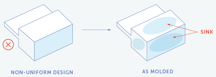
- Sink Marks: Sink marks can have multiple causes, but the most common one is a wall that’s too thick. Because resin cools from the outside, the material in the interior will remain fully molten even after the outer surfaces have solidified. As the core slowly cools, it contracts and pulls the outer faces inward, creating indentations. The effect is particularly apparent on flat surfaces. In most cases, thinner walls supported by ribs are better than thicker walls. Ribs won’t precipitate sink marks and the structure uses less material, too. Below is an example of sink-mark defects:
- Short Shots: Short shots occur when plastic solidifies before completely filling the mold. There are many potential causes for this, including wall thickness. If a wall is too thin, the plastic will not flow quickly enough to fill the whole mold before solidifying.
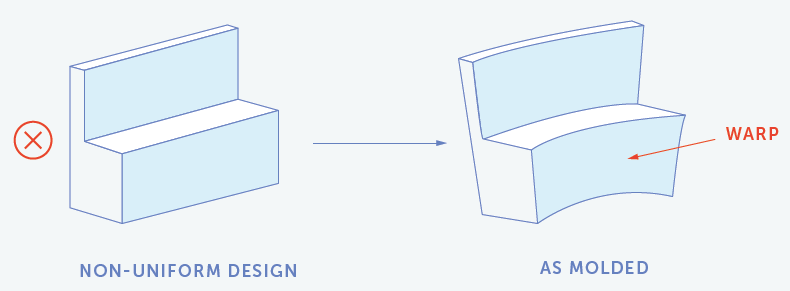
- Warping: Injection-molded parts will warp if their internal stresses are not balanced. These imbalances can be caused by non-uniform wall thicknesses. For example, when a thin wall section is abruptly followed by a significantly thicker section, the two will cool at different rates. The thicker section will cool more slowly than the thinner section, induce unequal shrinkage, and deform the structure. Below is an example of a warping defect:
Wall Thicknesses for Various Materials
The wall thickness chart below indicates the recommended thicknesses for some common injection-molding plastics.
Resin | Recommended Wall Thickness | |
| in | mm | |
| ABS | 0.045 – 0.140 | 1.14 – 3.56 |
| Acetal | 0.030 – 0.120 | 0.76 – 3.05 |
| Acrylic | 0.025 – 0.150 | 0.64 – 3.81 |
| Liquid Crystal Polymer | 0.030 – 0.120 | 0.76 – 3.05 |
| Long-fiber Reinforced Plastics | 0.075 – 1.000 | 1.91 – 25.4 |
| Nylon | 0.030 – 0.115 | 0.76 – 2.92 |
| Polycarbonate | 0.040 – 0.150 | 1.02 – 3.81 |
| Polyester | 0.025 – 0.125 | 0.64 – 3.18 |
| Polyethylene | 0.030 – 0.200 | 0.76 – 5.08 |
| Polyethylene Sulfide | 0.020 – 0.180 | 0.51 – 4.57 |
| Polypropylene | 0.025 – 0.150 | 0.64 – 3.81 |
| Polystyrene | 0.035 – 0.150 | 0.89 – 3.81 |
In addition to the recommended wall thickness, it’s important to consider a material’s flow characteristics. Each material has a maximum flow length for a given injection pressure and wall thickness — this is known as the flow ratio. Thin walls of greater length require greater pressure, which requires larger injection molding machines and more robust tooling, both of which increase costs.
Below you’ll find flow length ratios for some common plastics.
| Plastic | Flow Length Ratio |
| ABS | 30 – 50 |
| PS | 200 – 250 |
| PC | 30 – 100 |
| PP | 200 – 300 |
| PE | 250 – 275 |
| PMMA | 130 |
| POM | 100 – 200 |
| PA | 140 – 340 |
Design Guidelines for Part Wall Thickness
At minimal wall thicknesses, there are a number of design techniques that can optimize part strength.
- Ribs/Gussets: Ribs and gussets are used to support walls, bosses, and other free-standing features in injection-molded parts. Ribs primarily enable the reduction of wall thickness without sacrificing part strength. Fictiv recommends ribs no more than 50% to 60% of the wall thickness that they intersect, and rib height must be kept to a minimum.
- Bosses: Bosses are cylindrical features that reinforce fastener holes. Bosses should follow the same thickness guidelines as standard walls, and may be reinforced with gussets or ribs to further increase strength.
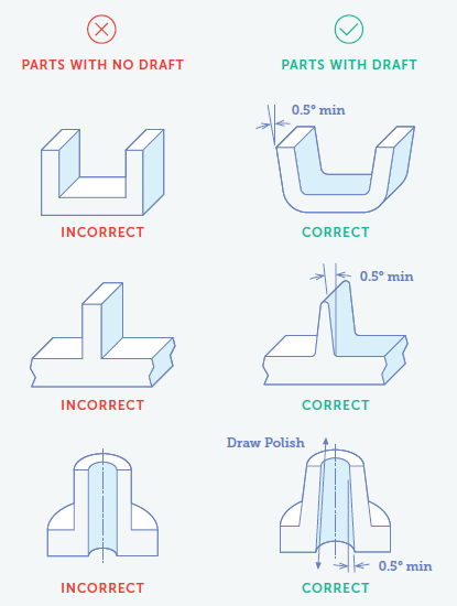
Draft Angles: Draft allows parts to be properly ejected from molds. Without a draft angle, parts may get stuck in the mold and can be damaged when ejected. Typically, walls and ribs must have draft angles of between 0.5% and 1% per side as indicated below:
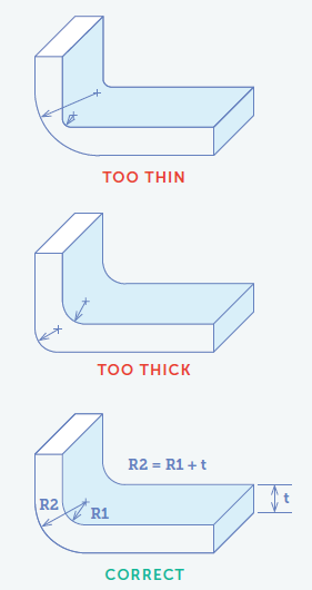
4. Corners: Corners should be rounded to prevent excessive stress concentrations that can compromise the parts’ strength and longevity, and sharp corners significantly increase mold costs. The following image illustrates a rule of thumb for sizing the radius on a corner that’s the nominal injection-molding wall thickness:
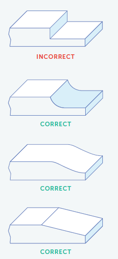
5. Thickness Transition: While walls of uniform thickness are often preferred, there are some situations where the wall thickness must vary for part functionally or strength. To prevent issues such as sink marks and warping, the walls must transition smoothly between thicknesses as indicated below:
Get DFM Feedback from Fictiv
The rules for a properly designed injection-molded part are well-established, but designing your parts well takes time to master. Good thing Fictiv is your operating system for custom manufacturing and we’re here to help!
Our experts have years of experience designing and manufacturing injection molded parts and you need only create a Fictiv account to get their expert guidance. We provide detailed DFM analysis of every part to help you optimize your injection-molding designs and accelerate your development cycles.


