Time to read: 6 min
One of the challenges with rapid prototyping is making sure that everything fits together properly. If the design team isn’t careful with its high-fidelity models, parts assembly may involve the use of a hammer – and sometimes in frustration.
With proper callouts, however, the secondary machining of 3D-printed and injection-molded parts gives designers a better tool. To ensure a perfect fit when a countersink hole isn’t needed, and to avoid the use of a hammer, the spotfaced hole is often the best solution.
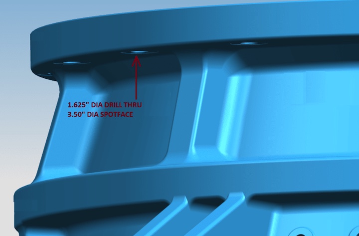
What is a spotface?
A spotface is a specific area of a part — a spot — that is “faced” (i.e., passed over with an endmill so that it’s flat). Often, it’s a best practice to create a spotface callout around a hole. This spotface must be big enough to encompass the head of the fastener or the face area of the contacting feature (e.g., the end of a boss that a screw is passing through). Spotfacing can also be used to make flat surfaces for mating faces. (We won’t cover that application in detail in this article, but be aware of the power of secondary machining processes.)
When is a spotfaced hole the right choice?
There are many different ways to approach functional design. One of the best methods to employ is elimination and reduction. Once you’ve established that a precision fit is desired, the design-by-elimination process is relatively straightforward. Use the simplified flowchart below.
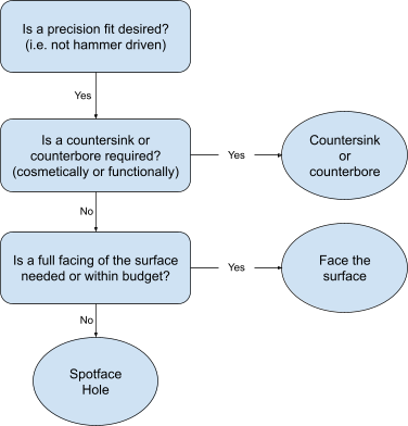
As shown in the flowchart, there are a few drivers in the decision-making process.
First and foremost, is precision needed? This question needs to be asked before the design is made. Otherwise, the hammer of frustration will make an appearance.
After establishing precision needs, the performance and cosmetic requirements need to be examined. (Use the countersink holes article for additional information.)
The last drivers are the scope of the precision and the cost. If only a small target area around the hole — let’s call it a spot — needs to be faced and the cost needs to be kept down, then a spotfaced hole is the solution.
How do you call out a spotfaced hole?
A spotface is a specific callout made on a control drawing or indicated in a CAD (e.g., SolidWorks) model. The GD&T symbol for a spotface is shown below.

A proper spotface callout requires, at a minimum, the diameter of the spotface to be called out. (A depth is not needed.) The spotface callout precedes a hole callout as the spotface is a secondary operation.
The simplest callout combination would be a through-hole with a spotface. In machining terms, this would entail a drilling operation followed by spotfacing using a spotface tool, which can be an appropriately sized end mill, counterborer, or an undersized endmill that performs an orbital pattern. Let’s use a metric example of a 2.2mm through-hole with a 5.5mm spotface. The GDT callout (without tolerances) would be as follows

What’s an example of when a spotface is the right choice?
The following is a modified example of a real-world scenario where a spotface is the right choice.
The problem
The company needs an enclosure for its new VR headset. The engineering team can’t use an off-the-shelf solution. Instead, this must be designed from scratch to fit with the custom mounting system. The engineering team needs 20x enclosures for field testing and evaluation. The sales team needs 30x to show off what the company is working on and drum up more investor interest.
The solution
First, the manufacturing method needs to be selected. This is where the establishment of primary operations occurs. The main options here are:
Since these are research and development activities, there is no need to proceed with injection molding. 3D-printed parts can be fragile, difficult to modify manually, and costly at this size. CNC machining is a great option but it is expensive for a 50x component need. Urethane casting is an excellent solution here. To play it safe, however, the design team orders a 3D-printed model for form and fit.
Everything looks and fits perfectly on the 3D-printed model! The team orders 2x urethane casted samples before proceeding with the order of 50x. The urethane parts just don’t fit right, however. The headset’s internals aren’t sitting properly and the enclosure has some gapping. Measurement and visual inspection of the parts yield nothing. What could be causing this?
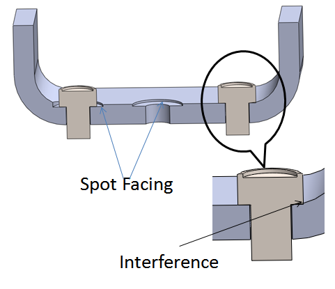
It turns out that the precision designed into the parts — suitable for injection molding, and needed for the mounting of components — was too much for the production method. (If only they’d used the flowchart above!) But the parts are durable, and they look exactly like the injection-molded production models will. The screws are not sitting flush. The slight aberrations in the surface around the screw holes is causing all of these misalignment problems. This can’t be solved with a hammer. It needs design refinement.
Because of this catch, the engineering team requests that secondary machining is performed on the parts: specifically, spotface callouts around the screw holes. Another 2x sets are ordered, this time with spotfaced holes, and everything fits! The precision of the secondary machining eliminated the gapping, and the internal components are now fixed in place precisely. It turns out that a water-spray test has no effect on these assembled VR headsets. The remaining 48x enclosures were ordered and no further issues were had.
This engineering team got lucky and their caution saved them. The piecemeal approach to ordering allowed them to catch the alignment issue caused by the lack of a spotface callout before everything was ordered.
What are some further considerations with spotfacing?
Spotface callouts are add-ons that become more important as the precision requirements increase. For example, if a chemical or vapor seal is needed, then high-precision injection molding may not be enough; a spotface is very likely needed to ensure a gapless seal that is closer to the CAD model. Similar to countersinks, there are other uses for a spotface besides making a level surface for a screw head to rest on. Of course, a washer or a standoff can be placed on a spotfaced area, but what if there is no need for a hole? Spotfacing of contact points can be incredibly useful.
There are some cases in engineering design where two flat surfaces need to contact each other and they must be truly flat. If there is one or more localized contact points, then spotface callouts are needed. The callout is exactly the same as shown above. The symbol refers to the secondary machining process of localized facing.
Flattening contact surfaces often fixes larger issues with a produced part. Produced parts never come out like the CAD model, but two flat contacting surfaces can be used to locate and anchor parts. For example, a large 3D-printed part may have a slight warp in one dimension. Using spotfaced contact points in this case will align the part as it is fastened together. As the part is fastened, the flat surfaces become parallel and allow for some sliding. This enables the assembled geometry to more closely match the CAD model.

Do you really need spotfaced holes?
The use of a spotface callout can make or break a design. Primary manufacturing methods are not enough; the value of secondary machining cannot be overstated. A spotface callout can be the difference between an assembly fitting perfectly without help and a hammer having to be resorted to. Taking into account the precision requirements and other needs of the project will help drive the design in the right direction. Always ask for an experienced second opinion. That second set of eyes saves a lot of time, money, and effort. Talk to an experienced Fictiv representative to determine if spotfaced holes are a good idea for your next project.
Fictiv is your operating system for custom manufacturing that makes procuring even the most complex parts faster, easier, and more efficient. Create an account and upload your design today to see what our instant quote process, design for manufacturability feedback, and intelligent platform can do for you.


