Time to read: 8 min
Product Concept Development
This article will take you through the process of physical product development, starting with the essential step of developing the product concept.
Problem Statement
What product would mechanical engineers want to have by their side at all times? That’s what I asked myself as I embarked on this design project.
As with many consumer products, the goal was to create something functional and aesthetically pleasing, which could also be branded and given out at trade shows. This product was intended to showcase Fictiv’s injection molding abilities while also providing an opportunity to explore design differences with other manufacturing processes.
Initial Brainstorming of Product Ideas
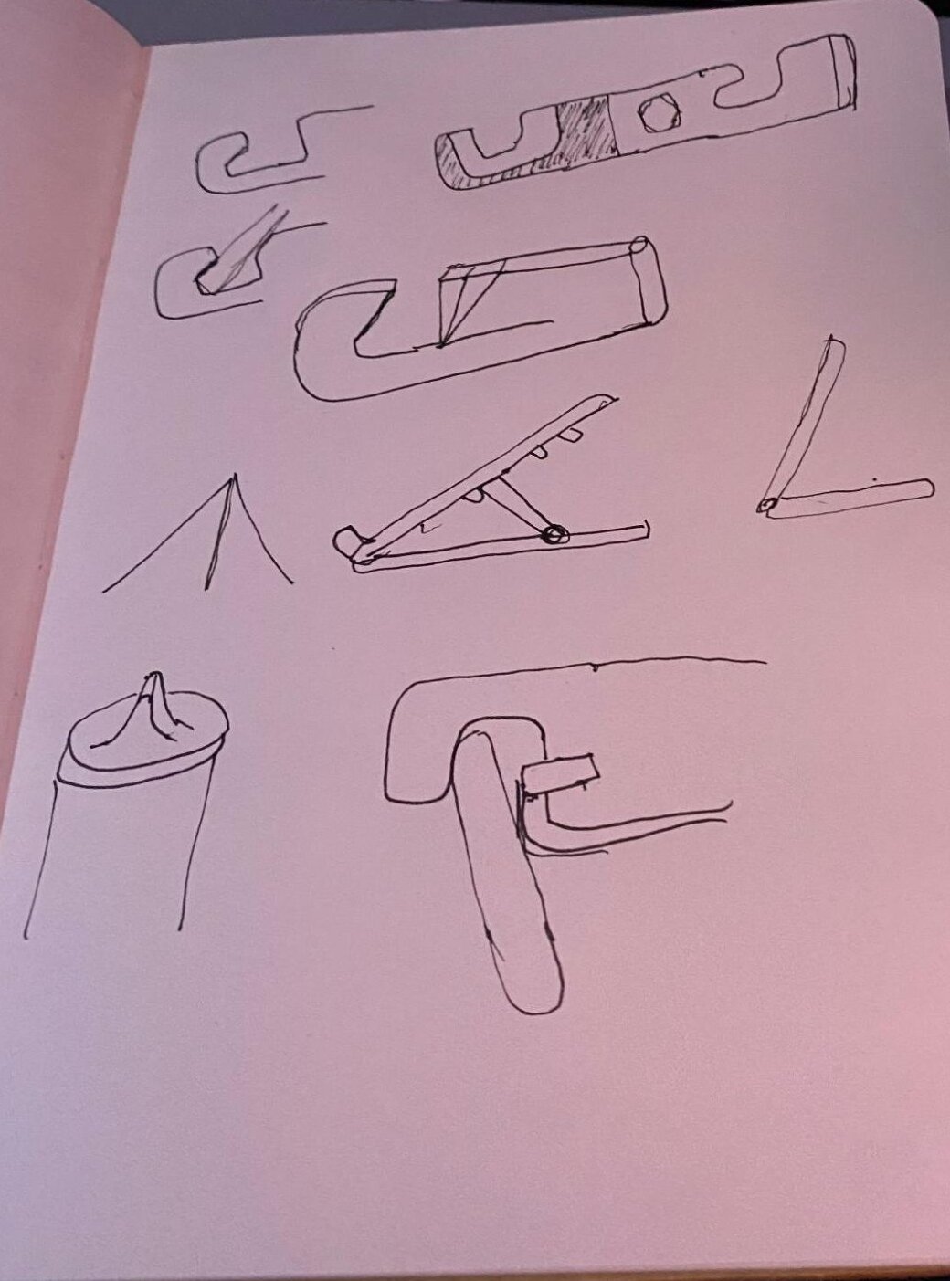
When starting to design a product, you may feel fairly confident about what you want to create. However, it’s important to dedicate time at the beginning of the process to identify and outline the key needs and constraints of the project. This includes brainstorming ideas, weighing the pros and cons, researching, and evaluating similar products on the market. For this project, an initial brainstorm yielded a few good ideas: a desktop phone stand, box-cutter, and multi-tool, among others.

Concept Selection
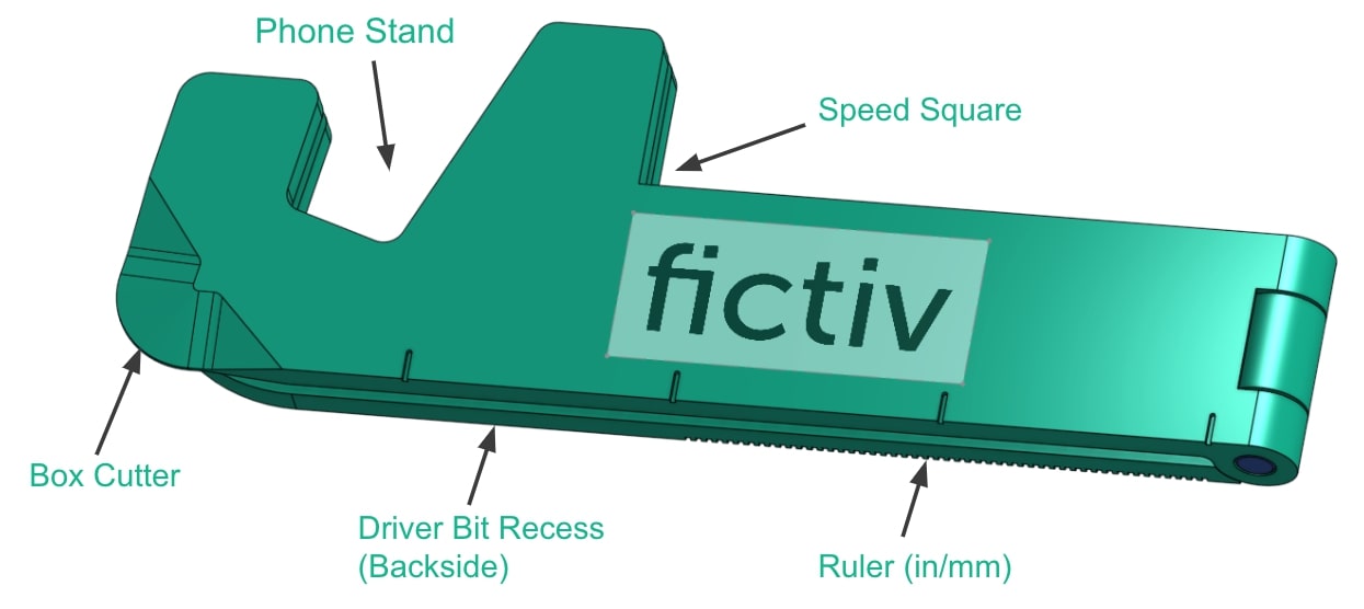
After evaluating these concepts, the concept was born to combine the features into one product that would be a smaller form factor for trade shows and explain key design topics and DFM for our manufacturing processes.
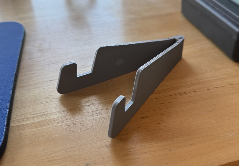
I like that this product can live on your desk and also be taken around with you in your pocket. It’s no racecar or robot, but it can be a handy tool as you run around the office slashing open boxes, checking dimensions, and making quick adjustments to your parts or assembly.
Hand Sketching for Concept Development
It’s good practice to hand-sketch your ideas upfront to see how they might look and come together. You don’t need to be the best artist in the world to get ideas across and think through them visually. Form factors and features can often be removed or recognized in this step, and time can be saved by realizing this with sketches before jumping into CAD.
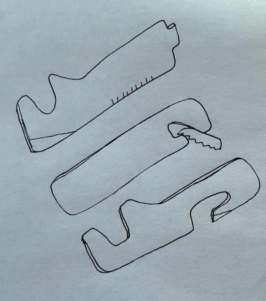
As the concept takes shape, it’s essential to weigh functional and aesthetic considerations that often compete with each other. This is a learned skill to balance the two using one’s inherent knowledge of mechanical properties and three-dimensional space. It’s beneficial to think through this early on, but realistically, the design will likely change further along in the process.
CAD: Bringing the Idea to 3 Dimensions
After doing some hand sketching and gaining a better idea of how the product will take shape, it’s time to start working with computer-aided design (CAD) software. Some prefer to begin working in CAD earlier than others. It is also common for an industrial designer to provide a preliminary aesthetic model or “shell” for a mechanical engineer to use as a starting point. I used Onshape for this project, which is one of many great CAD programs available.
The technique I used is called Master Modeling, which is a key aspect of top-down design. In this approach, a single part file—often referred to as a master or skeleton model—contains multiple interdependent solid bodies that are designed in relation to the master model. This ensures consistency and parametric control throughout the design process. Each solid body can then be exported as a separate part file and assembled into a multi-component assembly, while maintaining their original relationships and design intent. Additional modifications can be made in the separate part files as needed.
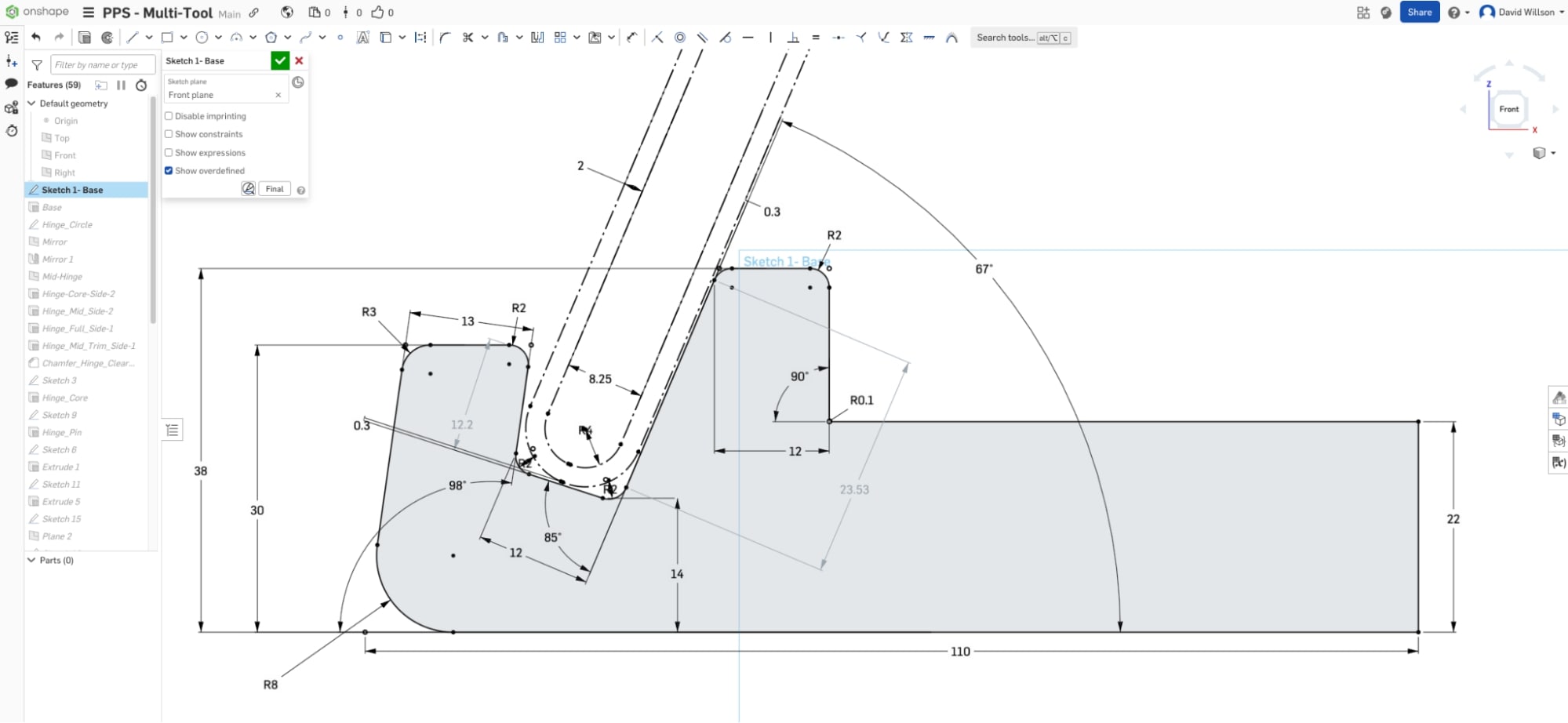
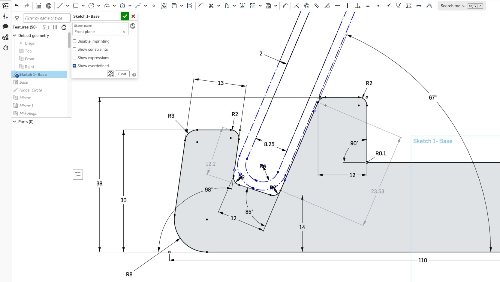
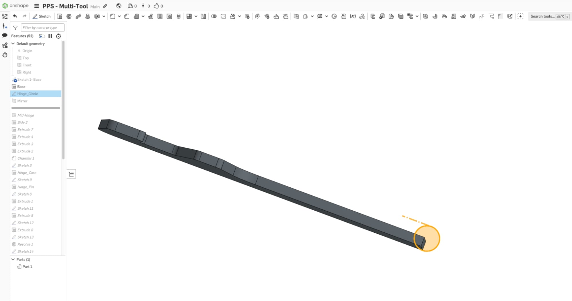
First Sketch: Skeleton
Start with a baseline “skeleton” sketch to establish the profile and overall dimensions of the product. This is typically a bare-bones sketch that everything else in the model tree is built off, so it must be robust and easily adjustable. The simpler it is, the more likely it will hold up to ongoing changes further down the line. Sometimes, a skeleton can be as simple as a series of lines, planes, or surface datums to drive the overall dimensions. In this case, I have included fillets in the first sketch for demonstrative purposes.
Using Fillets in the Sketch vs. After Solidifying
There are pros and cons of using fillets in the sketch or on the edge of the solid or surface. You can create them in the sketch to reduce the number of features in your model and easily visualize the overall form, but it can make it more challenging to create and change dimensions. In many cases, it makes more sense to add separate fillet features at the end of the model tree, or at least the smaller rounds that don’t make up the overall form. Both options can be done, depending on the product and manufacturing needs.
Functional Mating Features
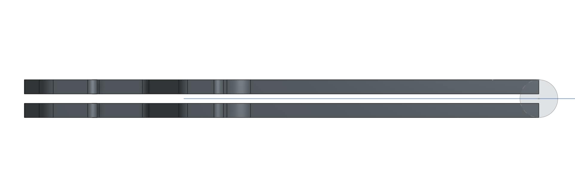
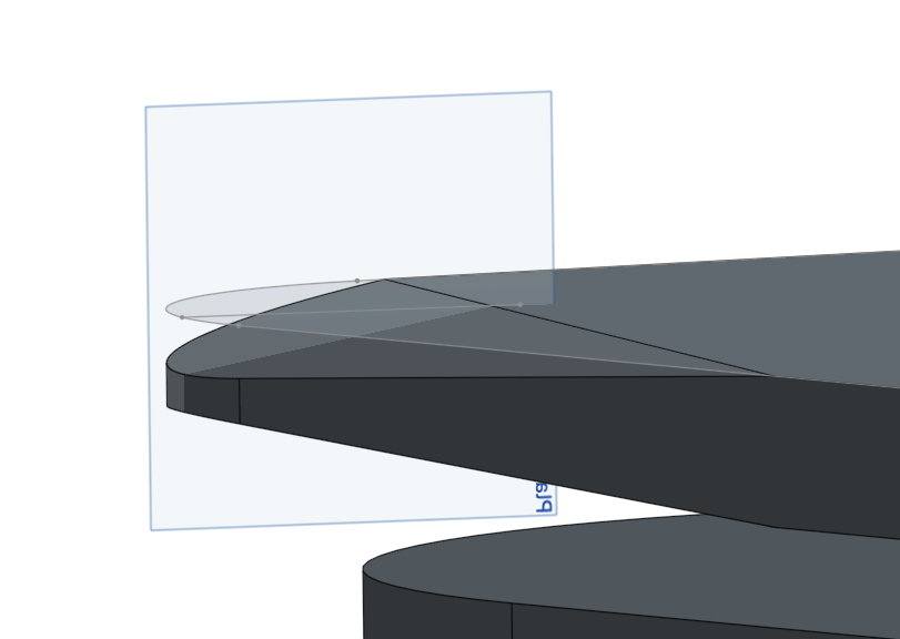
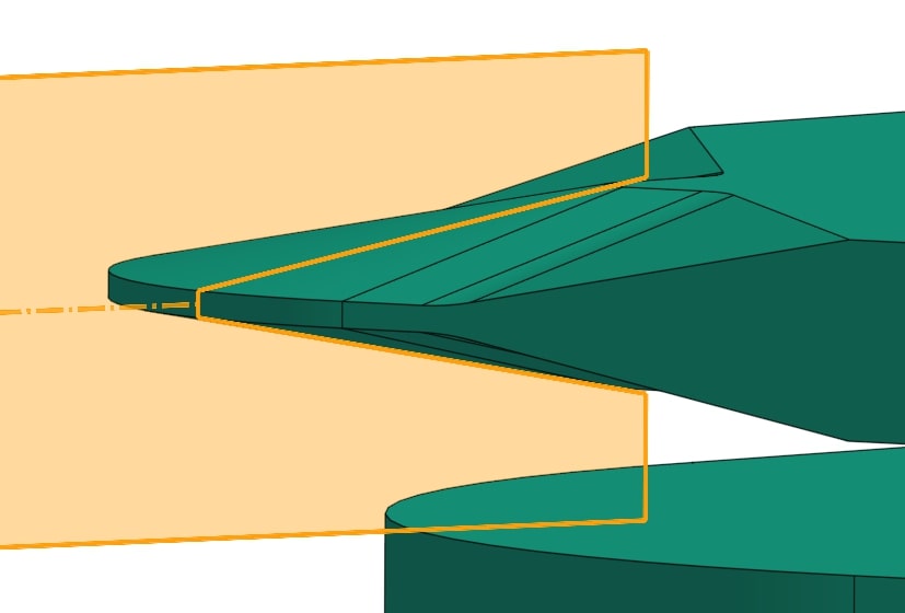
Create a reference sketch to make sure mating parts fit correctly. This can also be done in an assembly, but it is beneficial to be able to reference it with your initial skeleton sketch that drives the form.
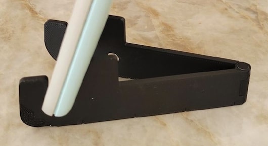
Here, I modeled the thickness of an iPhone 16 Pro and offset the phone profile to account for the thickness of a typical phone case. With this particular design, it’s challenging to account for every thickness of phone, case, and accessory possible. You can see how the difference in angle for the opening allows for variance with device thickness within a specific range.
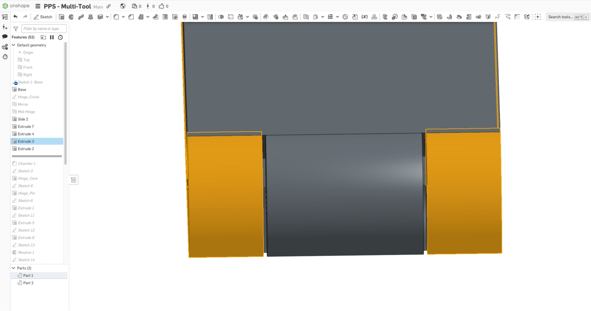
Extrude and Mirror
For a (primarily) symmetric part such as this, you will want to establish a mid-plane that half of the design can be mirrored around. To keep the mirror feature robust, you want it to be as late in the model tree as possible. This keeps the features you want on both sides ahead of the mirror so you don’t have to change or fix everything twice.
In this case, the mirror plane is driven by the hinge thickness, which is driven by the hinge pin diameter. There are some features that need to be done after the mirror.
Hinge Design
Set up a circular sketch to establish the hinge diameter, which drives the product’s overall width in its collapsed form. It’s important to consider the minimum thickness of each component, the nominal thickness of the main parts, and the tolerance stack-up of all components fitting together. Our tolerance analysis calculator is a great tool to help you see how your tolerances add up.
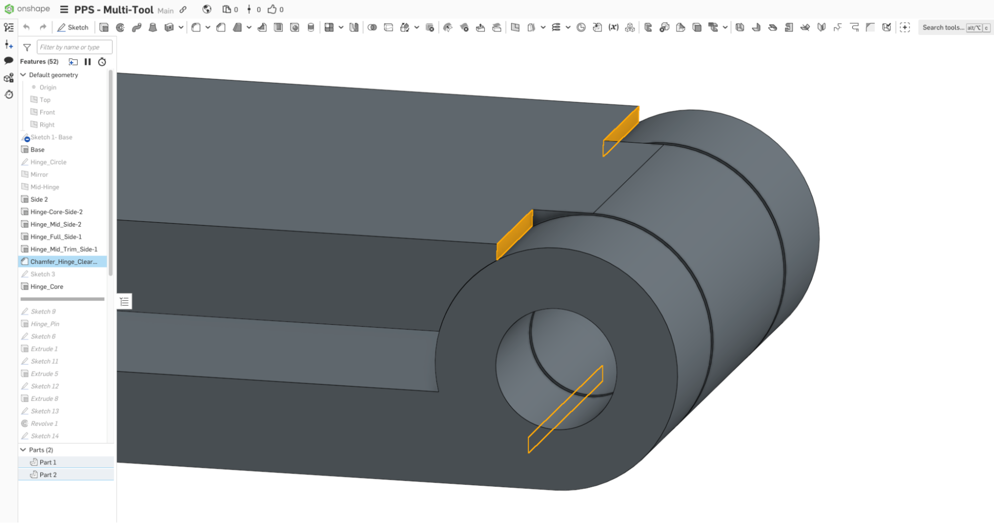
Next, the hinge is split.
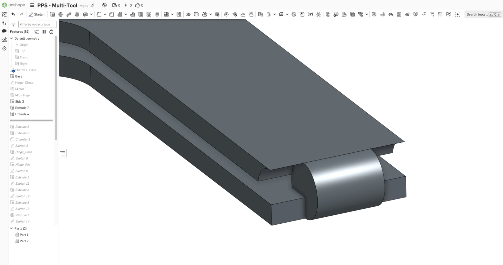
From the mid-hinge plane, a symmetrically extruded boss and cut create the hinge that is split across the two parts, with clearance to account for tolerances.
Sharp edges are removed to create clearance and a more durable edge that can be filled with material if molded.
Box Cutter Sharp
I played around with a few different locations for the box-cutter sharp, and in the end, this area made the most sense functionally. I physically tested the sharp profile with 3D prints to ensure it could cut through tape on a box.
This feature works with plastic material, but the cutting edge will be much more effective if made from a metal alloy. This profile is made from a swept cut with a 10-degree chamfer in preparation for it to be machined out of metal. Planning for process or material changes in the initial design phase offers versatility without compromising integrity.
Prototyping for Product Development
You will want to prototype as early and often as possible. I have a 3D printer, which helps because I can run prints while working on other tasks. Don’t have one? Well, with Fictiv’s 3D printing service, you can get parts in as fast as 24 hours!
Balancing Function and Aesthetics
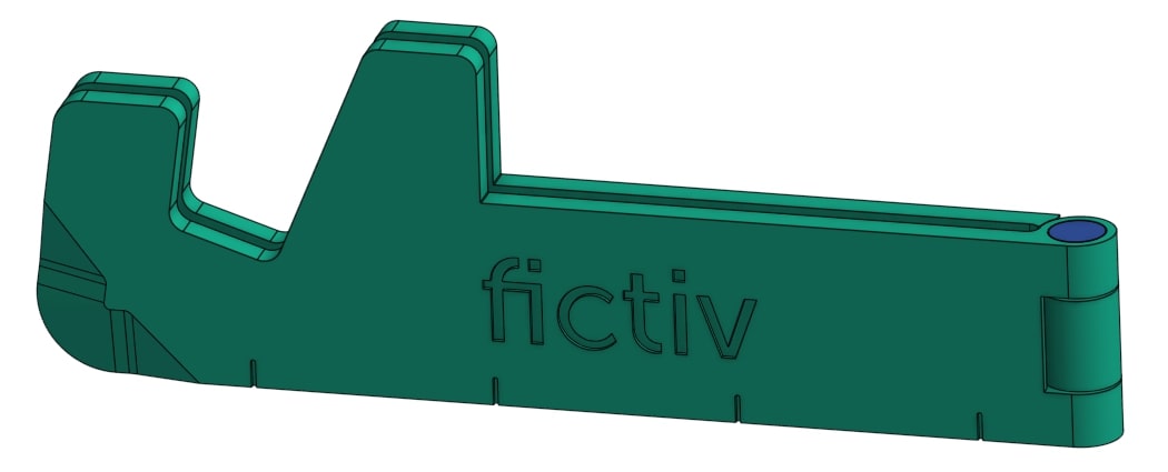
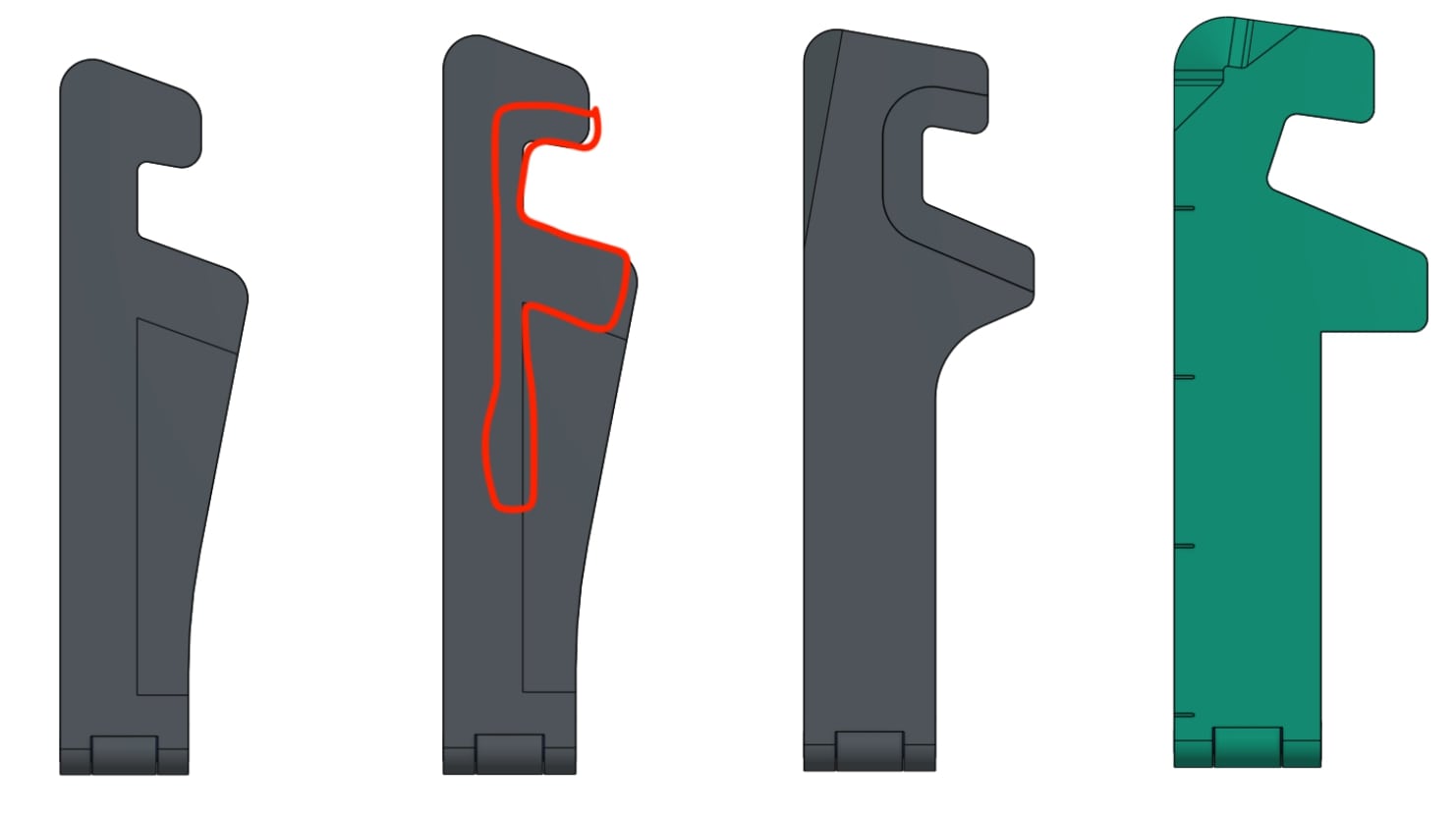
Once you have an initial working design or prototype, you may want to experiment with aesthetic changes and any functional tweaks you want to make. In this case, I saw an opportunity to mimic an F shape – inspired by “Fictiv.”
This is why it is so helpful to have a robust model, and the first sketch is so critical. When I first adjusted the sketch that wasn’t fully defined, the shape was broken.
The F shape took many forms as I balanced the round for the box cutter sharp, the round on the leading edge for pocketability (later becoming a sharp corner for use as a “speed square”), and the pocket for the phone itself.
Manufacturing Considerations
Early in the design process, it helps to consider how each component will be made and what materials you will use. In this case, I was thinking about structural parts that needed to be strong.
For example, with the box opener edge, a quick print confirmed that it was sharp enough to cut through box tape, but it was not durable. I determined that there could be a metal component insert-molded to improve the product performance and quality. I needed to then consider how large that component would be and where in the part it would reside. This will also be driven by DFM feedback, so it’s safer to leave more room than you may need, if possible.


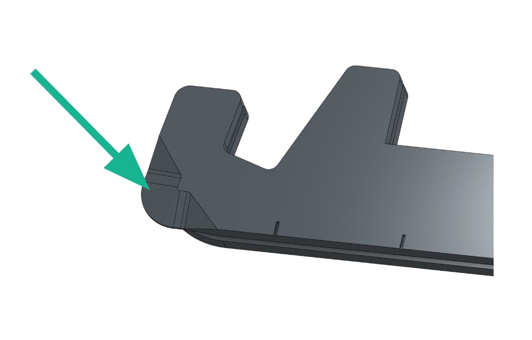
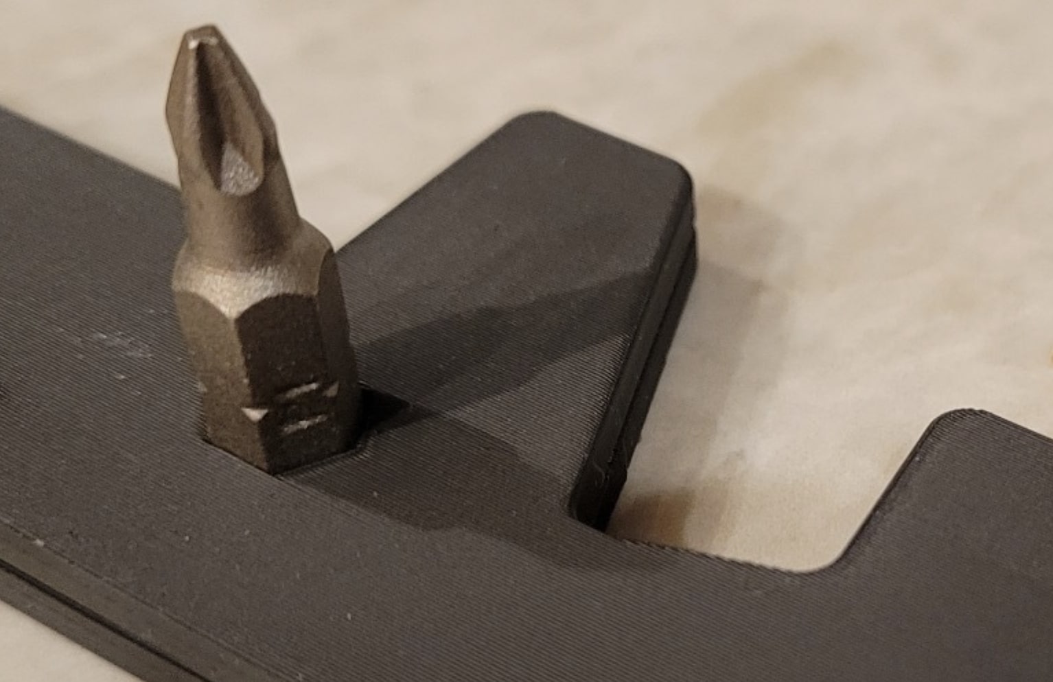
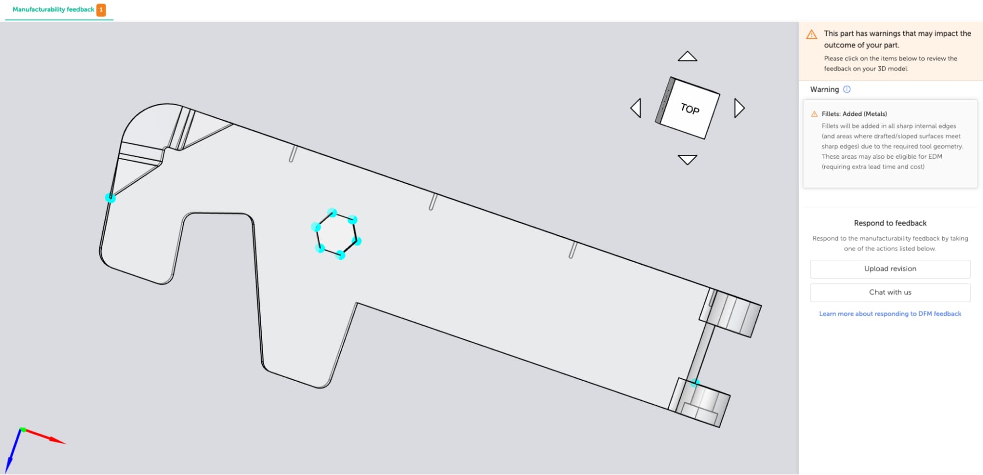
Other features I considered, like a bottle opener, would require it to be made of metal. The hex recess would also be more robust if made with metal. However, the shape with sharp corners is not machinable, and the design needs to be updated for that method by relieving the corners. Manufacturing feedback on Fictiv’s platform clearly highlights this, as shown in the image below.
Initial Design for Manufacturing (DFM)
Even though this first phase aims to test a 3D print or machined part, it helps to do a quick DFM analysis with the end manufacturing process in mind. In this case, a quick draft check is helpful with the potential for the part to be injection molded.
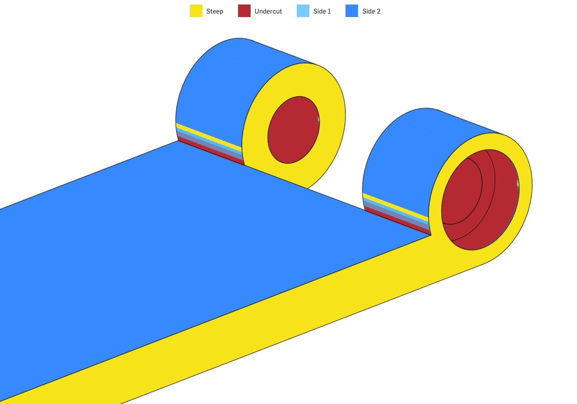
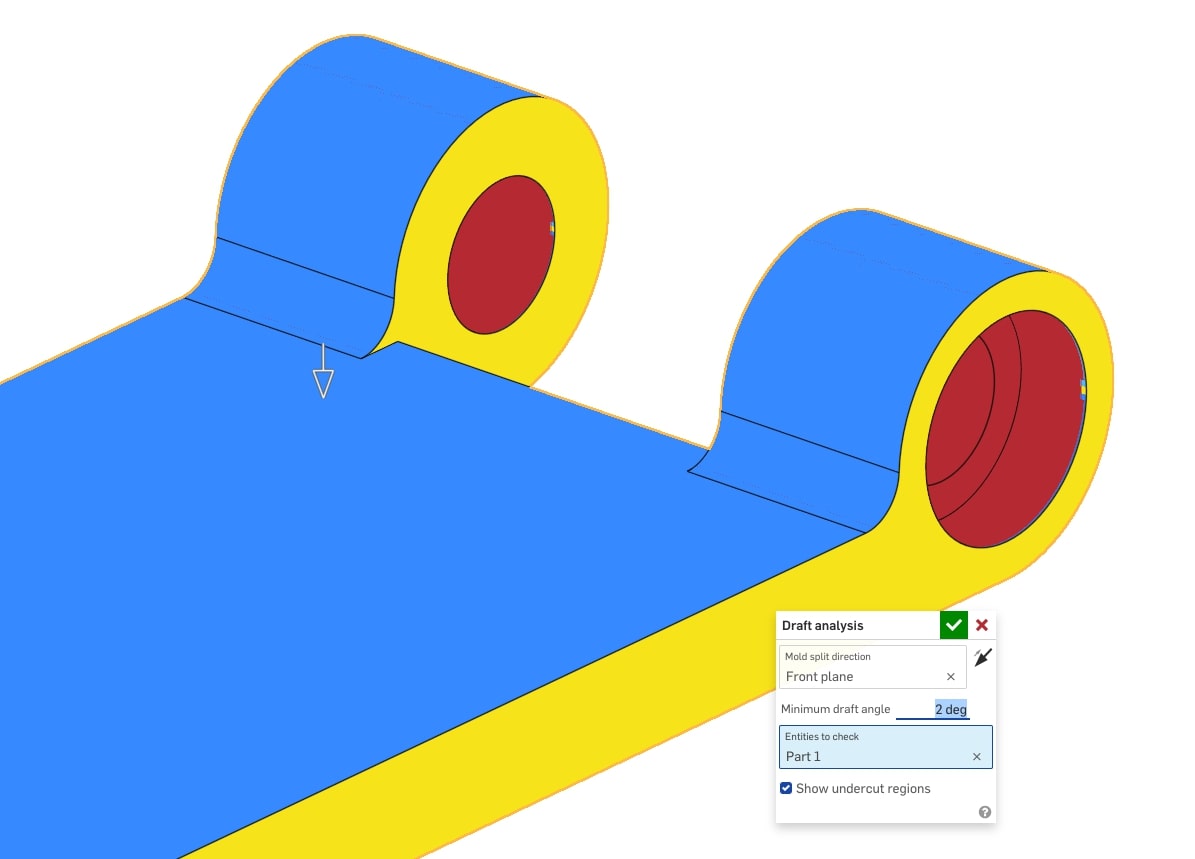
The flat sides of each part need draft, and the through-hole for the pin is an undercut that will need to be pulled on a slide in the tool. Due to the circular profile of the hinge, it creates an undercut. I added fillets to this area, not only to remove the undercut and create a necessary minimum draft angle but also to add strength to this section.
Download the File and Upload it to the Fictiv Platform
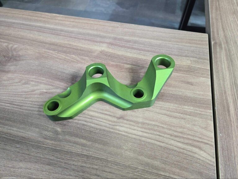
You can find the master model of the design here on the Onshape cloud-based platform and export each component as a .stl or .step file. Then, create an account and upload the files to our platform to be 3D printed or CNC machined. I recommend the Vero material for printing with PolyJet and PC or ABS material for machining. The prototypes pictured were made with a Bambu Lab Carbon X1C 3D printer.
You can create a copy of the Onshape document and make any changes you would like, including customizing it to the size of your phone if necessary. Please note that for features such as a tight-fitting hinge pin, dimensions may need to be adjusted to account for the tolerances of your manufacturing method.
Keep an eye out for the next chapter of this PD process series for more design and DFM insights as the product progresses to production quality.