Time to read: 5 min
Counterbore holes are popular for receding fasteners and seals in machined parts, especially in sealing applications, mechanical assemblies, and automotive parts. They have a non-tapered recessed area, so the heads of installed fasteners sit flush with the surface of the part.
In this article, we’ll define counterbore holes, explain when to use a counterbore, and describe how to call out a counterbore hole in your designs so that it’s manufactured properly.
What is a Counterbore?
Definition
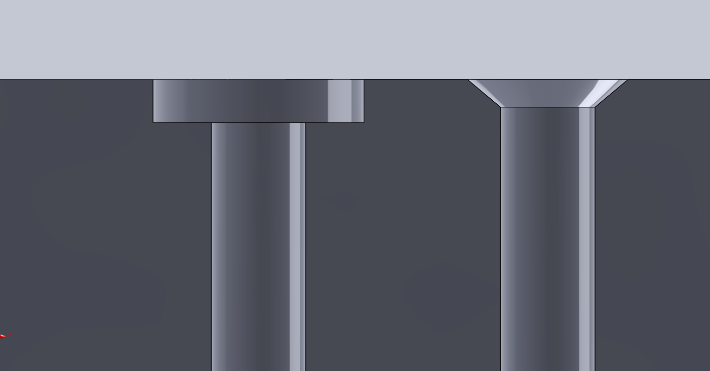
Left: Cross-section counterbore cut; Right: Cross-section countersink cut
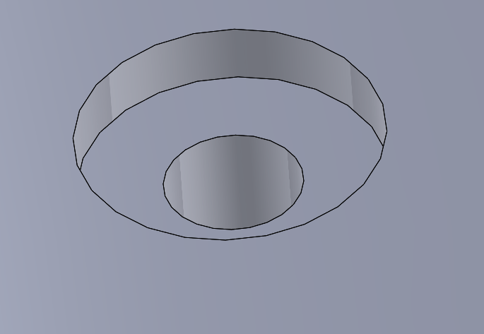
A counterbore is a cylindrical hole, with a flat bottom that is larger than and coaxial to another cylindrical hole below it. The counterbore serves to provide a recessed and flat surface for mating parts, and typically, socket head cap screws are used with counterbores.
Counterbore also refers to a tool used to enlarge the opening of a hole to create a flat bottom surface and allow socket-head screws to seamlessly fit with a part’s surface. While a counterbore may seem like a spotface, a spotface is less shallow than a counterbore. A spotface will often act as a flat mounting surface (for locating purposes), whereas a counterbore will recess a fastener head.
Counterbore GD&T Symbol

The flat-bottomed, cylindrical geometry differentiates a counterbore from a countersink, which has a conical bottom.
Components of a Counterbore Hole
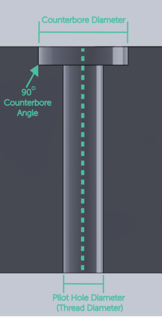
The graphic above shows how to fully define a counterbore hole with 3 critical dimensions:
- Counterbore diameter (this should be larger than the diameter of the fastener head, seal, or gasket)
- Counterbore angle (this is a standard 90 degrees for any fastener)
- Pilot hole diameter (defined by the fastener thread diameter)
You can use a drill bit to drill the pilot hole and then a counterbore cutter to make the counterbore if it’s within your tolerances for manufacturing. When CNC machining, a counterboring end mill tool is used, typically, to drill the countersink portion first, then the pilot hole.
When to Use a Counterbore
Counterbores are utilized to mill a cylindrical shape in a part in order to create a recess for:
- washers
- bolts
- gaskets
- o-rings
- socket head cap screws or fillister head screws
- specialty counterbore screws
- cosmetic or safety purposes when the top of a fastener head may snag on something or someone
The primary distinguishing factor for when to use a countersink vs. counterbore hole is the shape of the fastener head. Use countersink holes for conical or tapered head hardware and counterbore holes when the head is cylindrical or you’re utilizing a rigid washer or gasket.
A correctly executed counterbore will sit flush with the surface of a part, meaning the counterbore depth is only as deep as the head of the fastener and/or any additional parts like washers or gaskets. Counterbores allow for ease of installation (they are self-locating), a more streamlined appearance, and additional safety — things won’t get caught on fastener heads sticking out of a surface.
How to Specify a Counterbore
Most CAD programs, such as SolidWorks, have a built-in feature for creating counterbores in your model. While this functionality ensures your fasteners will fit in the pre-defined hole, it’s still important to understand the underlying principles and standards, such as ANSI or ISO, so that control drawings are properly defined.
Pro-Tip: Check out this article for more information on properly conveying design intent in manufacturing drawings.
Counterbores and their corresponding fasteners are well-defined by industry standards. As shown in the example graphic, you can easily specify the necessary features, such as angle, diameter, and pilot diameter to create a precise counterbore.
To correctly specify the counterbore your design requires, you should first consider the following:
- The standard that controls the design.
- The size size of the fastener that will go in the counterbore hole
- How tall the fastener head is
- How big the counterbore hole must be (the diameter of the fastener head plus the desired clearance)
It’s important to note that as an alternative to countersinks, the target angle of the wall of the larger diameter of a counterbore hole is consistently 90 degrees. While CAD tools can handle this difference without any issues, you must be mindful of the specs since they can change and affect the final product. As such, it’s crucial to properly call-out the counterbore hole using the expected drawing elements to avoid any potential issues.
Properly calling out a counterbore on an engineering drawing consists of four components:
- Diameter of the counterbore
- Depth of the counterbore
- Diameter of the smaller pilot hole beneath the counterbore
- Depth of the smaller diameter below the counterbore
Some sources leave out the depth of the smaller diameter hole (the pilot hole) but, it’s a critical specification and will always be called out alongside the counterbore dimensions. The symbol for a counterbore is ⌴ , and here’s an example call-out from a drawing containing a counterbore for a binding head machine screw:
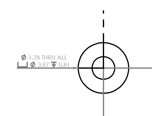
The drawing shows a 1.78 inch diameter thru hole underneath a 3.97 inch diameter counterbore, to a depth of 0.81 inches.
How to Determine Counterbore Sizing
Determining the size of a counterbore is simple when the size of a fastener is defined. Simply add tolerance for the diameter — or largest dimension for polygonal shaped fasteners — so it can fit within the counterbore diameter. Then add a little bit of room on the height of the counterbore to fit the height of the fastener head and any washers you may be adding.
Also, there are plenty of tables with counterbore hole sizing data (they even contain pilot hole sizing and depth as well):
- Counterbore Sizing for Socket Cap Head Fasteners (ANSI Inch)
- Counterbore Hole Size Chart for Socket Cap Head Fasteners (ISO 4762)
- Counterbore Hole Size Chart for Socket Cap Head Fasteners (DIN 912)
- Counterbore Hole Size Chart for Socket Cap Head Fasteners (JIS)
- Counterbore Hole Size Chart for Socket Cap Head Fasteners (GB)
- Counterbore Hole Size Chart for Socket Cap Head Fasteners (ANSI Metric)
- Counterbore Hole Size Chart for Low Socket Cap Head Fasteners (DIN 7984)
Fictiv – Complex Parts at Ridiculous Speeds
It’s always a good idea to get a second set of eyes on your designs before production starts, especially the eyes of a Fictiv applications specialist. That way you’re sure that you’ve properly called out features like counterbore holes in your designs.
And when you combine a clear drawing with our network of skilled manufacturing partners — which has experts in injection molding, CNC machining, 3D printing, and urethane casting — and you’ll get the high-quality parts you need, every time.
Create an account and upload your design today to see what Fictiv’s instant quote process, design for manufacturability feedback, and intelligent platform can do for you.