Time to read: 7 min
Once your plastic part design for injection molding has been completed and reviewed, and DFM feedback has been implemented and approved, the next step is to design your plastic injection mold: the tooling.
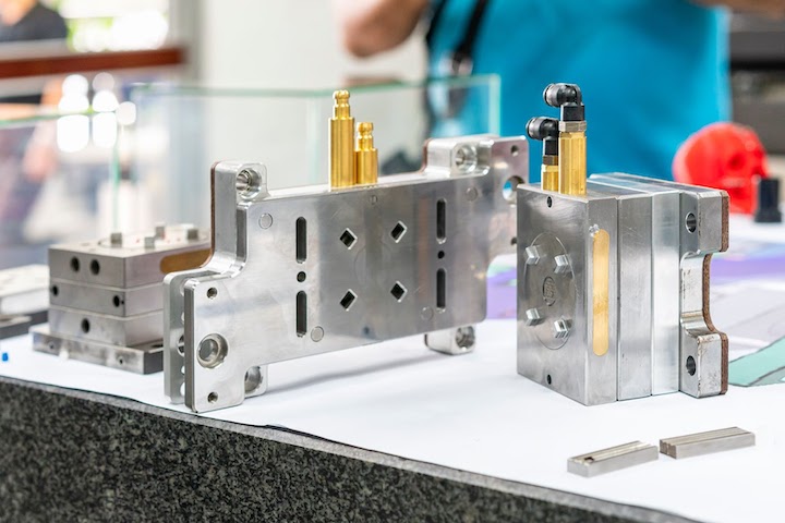
This may sound obvious, but quality plastic injection molded products are only made with quality injection molding tooling. Your tooling must be precise, yet able to handle repeated filling and releasing of plastic components.
A variety of tools and methods are used to manufacture plastic injection molded parts, such as the three-plate injection mold, overmolding, two-plate molds, and family molds. And as the complexity of a plastic component increases, the complexity of the mold required to produce it also increases. The molds themselves also have features and systems that perform certain functions when in use that complicates things further. Read on to learn our best tips for designing and manufacturing your next plastic injection mold.
Types of Injection Molding Tooling
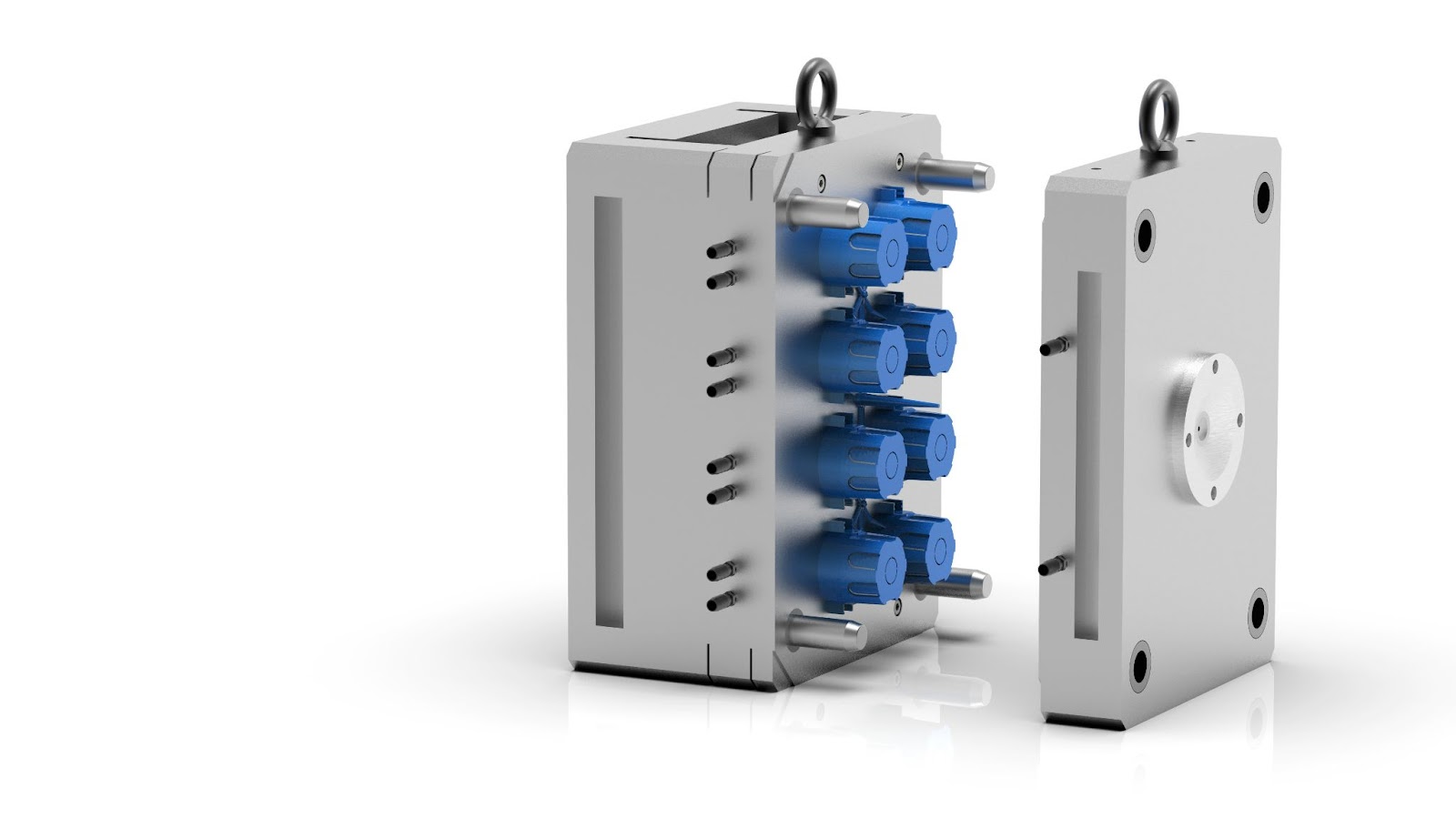
The basic construction of a mold consists of a cavity and a core. The cavity is a void for the formation of the external surfaces of the injection molded part. The core is the inverse that forms the internal structures and surfaces.

Two-Plate Molds
Two-plate molds are the most common injection molding tooling because they’re versatile and cost-effective. They’re comprised of two plates: a cavity mold plate and a core mold plate. The cavity mold plate provides entry points for the molten plastic to flow from the injection unit to the mold via a sprue, and then to the runner and gate. Two-plate molds also have a gate connected to the side of the cavity (the void within the injection mold) that is the negative of the desired plastic component’s geometry.
Three-Plate Molds
Three-plate injection molds offer extra flexibility in gate positioning and reduce post-processing because they don’t require manual excess material removal. A three-plate mold differs from a two-plate mold because it has more than one parting line and three distinct plates: the clamping/stationary plate, the center plate, and the front cavity/moving plate.
With this construction, the gate connects to the base of the cavity to allow for an even distribution of molten plastic. Three-plate injection mold tooling is advantageous for center-gated parts, but due to high shear rates, they aren’t recommended for shear-sensitive materials.
Overmolds
Overmolding is a specific type of injection molding that utilizes two molds to produce a part with different plastics molded together as one unit. The two molds can be 2-plate or 3-plate molds — typically the harder “substrate” plastic is molded first and then is inserted into the overmold tooling to add a second layer of plastic, often elastomeric in nature, to the part. Overmolding is used for ergonomic and aesthetic purposes in part molding.
Tips for Injection Mold Tooling Design
Mold Block Size
One of the first things to specify when designing tooling for an injection molded part is the overall size of the mold block.
- Choose too big of a mold and you waste money on excess materials and machining.
- Choose too small of a mold and your part may not be oriented in the most optimal way, which increases risk of premature mold failure.
Simply put, your mold block size should be just slightly larger than necessary and leave at least a 10 mm gap between the part’s exterior wall and the exterior mold block walls.
Parting Line Locations

Parting line location is dependent upon the part’s orientation within the mold block volume. Follow these tips to determine the optimal parting line orientation for your injection molding tooling:
- Strategically place parting lines such that your ejector pins can best eject the part from the mold.
- Select a parting line location that reduces the amount of hand-loaded (removable and floating) inserts.
- Leverage parting lines for placement of required hand-loaded inserts. For example, removable inserts for threaded features are not suited to withstand a straight pull ejection.
- Consider using floating inserts placed through a parting line face to replace a side action component (if possible), such as for a through hole in the part.
- Remember that gates should be placed on the parting line so that the location functions well for both the gates and the parting line.
- Locate the parting line to reduce undercuts that complicate part removal and may require additional removal mechanisms.
Pro-tip: try a raised parting line by creating a recessed area away from the parting edge. This raised parting line significantly increases clamp tonnage control and provides a better seal for low viscosity plastic.
Designing for Part Ejection
Here are our main tips for designing molds that make beautiful parts and eject them cleanly:
Pin Location
Determining ejector pin locations may seem simple: make sure that all locations are covered by plastic material. However, ensuring that the pin locations are thoroughly covered is a bit more complex. Try to incorporate ejector pin location into the component’s design — it’s natural for the ejector pins to leave marks on the plastic component’s surface, but the marks can be integrated into the part’s aesthetics.

Ejector pins can be utilized to perform venting at locations where there are air traps, and they also self-clean with each ejector stroke.
Draft Angle
Ensure the correct draft angle on the walls of the mold for easy plastic component ejection. We recommend a minimum of 0.5 degrees to around 2 degrees. The optimum target value for most cases is a draft angle of 1.5 degrees for depths of up to 2 inches. A good rule of thumb is to add on an additional degree of draft for each additional inch of depth.
Also, increase draft angle for parts with texture. Both the injection mold tooling and injection molded part design must incorporate sufficient draft angles or you risk the part getting stuck in the mold.
Ejection Method
Consider all of the possible ejection methods available. You can use a single method or a combination of methods such as ejector pins, ejection fixtures, compressed air, ejector plates, or even hand removal.
Wall Thickness
In general, the thinner the part walls, the larger the ejectors and ejector surface area you need to reduce the chances of damaging the parts when ejecting them from the mold.
Air-poppet Valves
Don’t be afraid to incorporate off-the-shelf components such as air-poppet valves that reduce the chance of a vacuum during part ejection.
Pro-tip: while undercuts are possible with injection molding, it’s wise to work to reduce or eliminate them because they increase mold complexity and maintenance frequency, which increases costs.

Runners
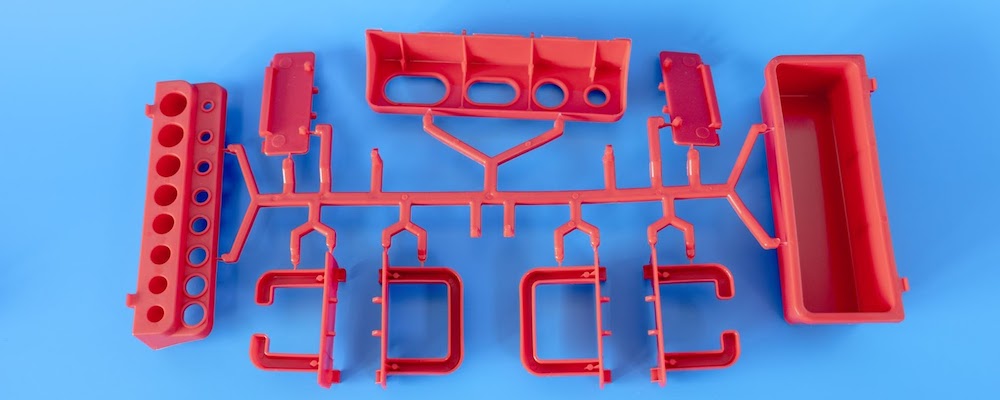
Runner misalignment in the mold block and the frame can be detrimental to the quality of the final molded parts. The runner start locations should connect to the targeted gate locations as the runners move molten plastic along channels machined into the parting line. Runner size plays an important role in injection molded part quality and efficiency of the molding process:
- Runners that are too thin may cause processing problems such as excessive filling pressures.
- Runners that are too thick can increase cycle time and increase costs due to extra material waste.
Round runners are the most efficient, but a trapezoidal shape with a rounded bottom is less complex to machine and provides efficiency gains during injection molding. Runners should be at least as thick as the wall thickness of the parts, and the thickness should be increased for longer runners.
Gates
Gates are the connecting features between the runners to the injection molding cavity. They reduce the effort required to separate the injection molded part from the runner system and prevent pressurized molten plastic from back-filling after the packing and holding phases.
Here are our best tips for gate design:
- Gates should be thinner than the runner and part wall unless you are utilizing unfilled materials. In such cases, the gate should be greater than half the part thickness, or for highly cosmetic parts, the gate should be ⅔ of the part thickness.
- Most gates should feed directly into the parting line.
- Utilize edge gates for large parts and shear-sensitive or high-viscosity materials.
- Utilize chisel gates for thick-walled parts and for a more refined cosmetic finish.
- Tunnel gates are beneficial for reaching portions of the mold that are not located on the parting line.
- Reduce the volumetric flow rate through gates to reduce potential molding problems.
- Increase the size of gates when wall thickness is decreased.
- If your part has varying wall thickness, position gates at the thickest walls to avoid packing problems and sink.
- Do not place gates in areas that will be subjected to high-stress levels.
Ensuring Proper Ventilation
Ensuring that your molten plastic can sufficiently and thoroughly fill all the voids within the cavity is critical to the success of injection molded part production. Since the molten plastic needs to displace the air to flow through the mold, increasing the number of vents decreases the injection pressure. Vents may take the form of inserts, pins (vent/ejector), vent holes, or even surface vents.
Follow these tips to ensure your injection mold tooling has proper ventilation:
- Utilize inserts and ejector pins to create vents when possible.
- Add ventilation at the end of the molten plastic fill to ensure the mold completely fills.
- Add ventilation to all features that are recessed and/or greater than 10mm deep.
- Start your vents out shallow (i.e. less than 0.0020 inches deep for amorphous resins) up to the first quarter inch of the vent length.
- When you add part volume and/or filling speed, add vents.
- Flash may occur if your vents are too deep, so restrict their depth as needed.
- Reduce the number of vents when molding materials with flame retardants or other additives that can cause the molten plastic to boil to the surface and deposit on vents.
Pro-tip: set up a master model template as an evergreen reference for future injection mold tooling designs. This template should include the runner, ejector pin, and mounting locations.
This article is an introduction to injection mold design, so if you want to learn more, check out these trusted sources for more information:
Start Your Next Injection Molding Project With Fictiv
If you’re ready to plan your next injection molding project, look no further than the experts at Fictiv for high-quality injection molded parts.
Fictiv is your operating system for custom manufacturing. We provide designers with DFM feedback about undercuts, threads, and other part features that can affect part ejection — and our expert injection molding guidance will help you make the right choices to create molds that deliver high-quality parts. Regardless of your order volume, Fictiv will help you streamline your workflows to reduce costs and shorten timelines.
You can learn more about our injection molding capabilities here and then create your free Fictiv account to request a quote!


