Time to read: 6 min
Let’s say you designed a mechanical assembly that requires some sort of mechanical sealing. Or you have a maintenance project that requires additional sealing to a new joint. Perhaps your assembly has a fluid reservoir, requires cooling fluid to pass through, or you’re joining two components together and need them to sit flush. To solve those problems, your first step is choosing the right type of mechanical seal.
O-rings are reliable and affordable, which is why they’re a popular solution. But you need a good groove design for the O-ring to do its job properly. This guide will walk you through our best tips for designing O-ring grooves.

What is an O-Ring (Refresher)
An O-ring is a circular piece of elastomer material that’s used to form a mechanical seal resistant to pressure that seals off mating components. Some O-rings can withstand high pressures in the range of a few thousand PSI. The groove that the O-ring fits into is also known as the gland.
O-Rings vs Gaskets
While O-rings and gaskets may seem similar, they are actually different methods of mechanical sealing. An O-ring is a type of gasket, but not all gaskets are O-rings. Gaskets can be made of many materials, including metal, while O-rings are only made of elastic materials. O-rings are also specifically circular in shape, whereas gaskets take the form of many cross-sectional shapes. That’s why gaskets are used in applications where sealing is needed for complex mating surfaces. O-rings are more standard and are used for simpler mating conditions.
O-Ring Groove/Gland Shape
The most important consideration for gland design is that it allows for proper and complete compression between the groove and the surface mating to it. Otherwise, the shape of the groove itself is not important. The shape of the O-ring groove depends on the application for the O-ring and can range from triangular to rectangular to dovetail.
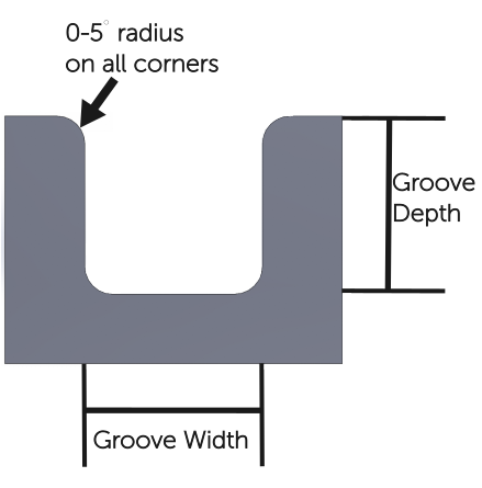
Generally, it’s good to focus on a groove shape design that’s easy to machine without sharp edges that can cause O-rings to deteriorate. Specifically, every sharp corner needs an O-ring groove radius and all interfacing corners should be chamfered or rounded to limit damage to the O-ring while installing it.
One of the most common O-ring groove shapes is a rectangular divet with rounded edges. This design allows for simple installation and uniform compression on all three sides of the O-ring that interface with the gland. See the example shape below:

O-Ring Groove Width
The first O-ring groove dimension we will cover is the O-ring groove width. The horizontal span of the groove should be sufficient to allow for full expansion of the O-ring within the groove. The horizontal span should only allow for a 5% expansion of the O-ring diameter. The OD (outside diameter) of the gland should be larger than the ID (inside diameter) of the O-ring so that the O-ring is always stretched when installed.
For cases where an O-ring is not installed in a gland, the O-ring interface should be designed so that it doesn’t require more than a 100% stretch when an O-ring is installed. The ideal number for the O-ring stretch, when installed in a gland, is not greater than 5%. Minimizing the installation stretch is done by correctly specifying the gland ID to accommodate the O-ring diameter. You can use the following equation (O-ring groove width calculation starting point) to set the requirement:
Minimizing installation stretch can prevent an excessive buildup of stress in the material, reduce the cross-sectional area and reduce the % squeeze of the O-ring. Another important rule to follow is to keep the percentage reduction in the cross-sectional diameter to around 50% of the percentage diameter stretch.
O-Ring Gland Width for Liquids versus Gases
In general, an O-ring gland for a liquid fluid should be larger than one used for gas — the liquid interfacing O-ring should be about 10-20% larger.
O-Ring Groove/Gland Volume
The best rule of thumb to follow for groove dimensions stems from specifying the correct amount of volumetric space for the O-ring material to fill the groove. This is necessary to ensure room for the O-ring’s thermal expansion (elastomers expand around 10 times more than metals), swelling due to soaking up fluids, and increasing width due to O-ring squeeze. The optimal ratio for O-ring gland volume is 15-25% empty space and 75-85% spaced filled by the O-ring material. The equations below calculate the gland fill percentage:
Pro-tip: when designing any component, especially an O-ring groove, utilize technical data sheets, industry specifications and other resources for guidance on your specific groove interface and type. This article doesn’t cover all the scenarios, but there are many publications that do.
O-Ring Groove/Gland Depth
The depth of the O-ring groove depends upon the width of the O-ring and the amount of compression that is best for your application. A specific compression ratio should be maintained in order to provide sufficient sealing without compromising the integrity of the elastomer material. The compression ratio may be calculated with the following equation:
Utilize the following compression ratios as starting points:
- For rotary O-rings: a compression ratio of 0-10%
- For reciprocating O-rings: a compression ratio of 10-20%
- For a static male to female mating interface: a compression ratio of 18-25%
- For a face seal: a compression ratio of 20-30%
Static vs Dynamic O-Ring Groove Design Considerations
Static O-ring applications — where the two components being sealed together don’t move — are the most common use for elastomer O-rings. Dynamic O-ring applications are utilized to seal two moving parts (with respect to each other). Both applications have their advantages and disadvantages. For example, wwelling is more likely to occur with a static O-ring, while material deterioration is more likely in a dynamic O-ring application. A static O-ring is an axial, radial, crush, or dovetail seal, where there’s pressure on the top and bottom of the O-ring. A dynamic O-ring forms a reciprocating, rotary, or oscillating seal that has alternating pressure on the O-ring in a back-and-forth manner.
Radial squeeze applications are often recommended over axial squeeze applications for static seals because they depend on the groove dimensions to maintain sufficient sealing and they are easier to use when parts are being modified. For static sealing applications, a groove surface finish of 63 rms is recommended for the sides and 32 rms for the bottom of the gland. For dynamic O-ring applications, it is recommended that any component which interfaces with the O-ring have a surface finish of 16 rms or smoother.
Start Your Next Project With Fictiv
O-ring groove design is critical when you’re mechanically sealing parts, and the experts at Fictiv are here to help — after all, Fictiv is your operating system for custom mechanical parts.
With our design and manufacturing expertise, innovative platform that provides instant DFM feedback, full production visibility, and quick turnaround times, manufacturing O-ring grooves for your parts is easier than ever! Our manufacturing network of highly skilled and vetted manufacturing partners can perform the precision machining you need for your next project. Upload a part and get an instant quote today.


