Time to read: 8 min
Injection molding tolerances are acceptable variations in size for part features and overall dimensions. They are expressed as plus or minus (±) values in millimeters or inches and vary by the type of material that’s used and the overall size of the part.
Part designers add tolerances to CAD files to tell an injection molder the amount of variation that’s allowed. In turn, injection molders use tolerances during design for manufacturability (DFM) reviews and to make tooling and processing decisions.
As a rule, parts with tighter tolerances are more expensive because they have stricter tooling and processing requirements. Mold quality is critical, as are proper cavity fill rates and consistent cooling temperatures.
Even with the best injection molding equipment, process repeatability varies. A skilled molder can calculate shrinkage rates for various plastics, but your design decisions affect part shrinkage and, ultimately, which tolerances are achievable. If an injection molding material has a higher shrink rate, tolerances are harder to control.
This article examines the importance of injection molding tolerances and their relationship to tolerance stack-ups. It also explains how part tolerances are specified and describes the factors that affect them. In addition, there’s a section for designers with frequently asked questions (FAQs).

Tolerances and Tolerance Stackups
Many injection molded parts are used in larger assemblies. A tolerance stack-up refers to how all assembled parts must fit together. Because each component has its own tolerances, designers need to account for the cumulative effect of dimensional deviations.
Consider the example of three injection molded parts that are bolted together. Each part has a hole with tolerances within the dimensions you specify. That’s great, but all three holes still need to align so that a fastener can pass through them.
Download Fictiv’s Tolerance Analysis Calculator
Types of Injection Molding Tolerances
There isn’t just one kind of tolerance for an injection molded part. Rather, there are tolerances for specific part features. Here are some of the most common.
- Dimensional: Overall sizing of the part. Increased part size results in larger shrinkage during cooling. This is why injection molding tolerances are listed for specific size ranges.
- Straightness or Flatness: Covers the general warping of large, flat areas. Mold design features like gate location and uniform cooling can reduce warpage.
- Hole Diameter: Larger holes need a larger tolerance range due to increased shrinkage.
- Blind Hole Depth: Blind holes require cantilever-type features in the mold. If the plastic is injected at high pressure, the pin inserts can deflect, and the deeper the hole, the higher the likelihood of deflection.
- Concentricity/Ovality: A large cylindrical part with a thin wall can shrink unevenly so that the part loses its circularity.
Injection molding tolerances aren’t just about part features. They can be divided into commercial and fine tolerances depending on the amount of precision that you need.
- Commercial tolerances are less precise. They require lower-cost molds and produce lower-cost parts.
- Fine tolerances, also called precision tolerances, provide a tighter tolerance band which ultimately makes the mold and subsequent parts more expensive.
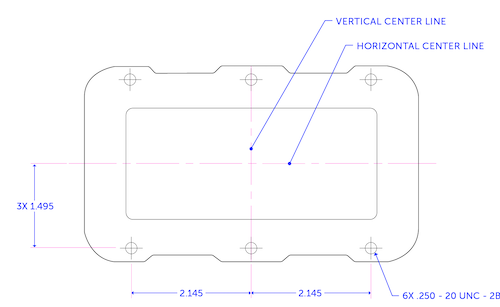
Mold Tolerances by Feature Size and Material
Part tolerances are a function of mold tolerances. Yet mold tolerances must account for the desired feature sizes and the injection molding material.
Tables 1, 2, and 3 below contain commercial and fine tolerances for common injection molding materials and specialty plastics and polymer blends. If you’re unfamiliar with the acronyms for these materials, the list below explains what they mean.
- ABS is acrylonitrile butadiene styrene.
- ABS/PC is a blend of ABS and polycarbonate plastic.
- HDPE is high-density polyethylene (HDPE).
- LDPE is low-density polyethylene (LDPE), a type of polyethylene.
- PA plastic is more commonly known as nylon.
- PA GF 30% is glass-filled nylon, where glass fibers represent 30% of the compound.
- PC is polycarbonate.
- PMMA is more commonly known as acrylic.
- POM is polyoxymethylene (POM), an engineering thermoplastic.
- PP is polypropylene.
- SAN is styrene acrylonitrile (SAN).
The Society of the Plastics Industry (SPI), a U.S.-based trade association now known as the Plastics Industry Association (PIA, or PLASTICS), defines typical tolerances. Because these are typical values, it’s essential to discuss them with your mold manufacturer.
Dimensional Tolerances (mm) |
||||||
Type: | Commercial |
Fine |
||||
Feature Size: |
1–20 mm |
21–100 mm |
101–160 mm |
For every 20 mm over 160 |
1–20 mm |
21–100 mm |
|
ABS |
0.100 | 0.150 | 0.325 | 0.080 | 0.050 | 0.100 |
ABS/PC | ||||||
HDPE | 0.125 | 0.170 | 0.375 | 0.100 | 0.075 | 0.110 |
LDPE | ||||||
PA | 0.075 | 0.160 | 0.310 | 0.080 | 0.030 | 0.130 |
PA GF 30% | 0.060 | 0.120 | 0.240 | 0.080 | 0.030 | 0.100 |
PC | ||||||
PMMA | 0.075 | 0.120 | 0.250 | 0.080 | 0.050 | 0.070 |
POM | 0.075 | 0.160 | 0.310 | 0.080 | 0.030 | 0.130 |
PP | 0.125 | 0.170 | 0.375 | 0.100 | 0.075 | 0.110 |
SAN | 0.100 | 0.150 | 0.325 | 0.080 | 0.050 | 0.100 |
Table 1: Dimensional Tolerances
Straightness/Flatness Tolerances (mm) | ||||
Type: | Commercial Tolerance | Fine Tolerance | ||
Feature Size: | 0–100 mm | 101–160 mm | 0–100 mm | 101–160 mm |
ABS | 0.380 | 0.800 | 0.250 | 0.500 |
ABS/PC | ||||
PA | 0.300 | 0.500 | 0.150 | 0.250 |
PA GF 30% | 0.150 | 0.200 | 0.080 | 0.100 |
PC | ||||
POM | 0.300 | 0.500 | 0.150 | 0.250 |
PP | 0.850 | 1.500 | 0.500 | 0.850 |
SAN | 0.380 | 0.800 | 0.250 | 0.500 |
Table 2: Straightness/Flatness Tolerances
Hole Diameter Tolerance (mm) | ||||||||
Type: | Commercial Tolerance | Fine Tolerance | ||||||
Feature Size: | 0.3 | 3.1–6 | 6.1–14 | 14–40 | 0.3 | 3.1–6 | 6.1–14 | 14–40 |
ABS | 0.050 | 0.050 | 0.080 | 0.100 | 0.030 | 0.030 | 0.050 | 0.050 |
ABS/PC | ||||||||
HDPE | 0.050 | 0.080 | 0.100 | 0.150 | 0.030 | 0.050 | 0.050 | 0.080 |
LDPE | ||||||||
PA | 0.050 | 0.080 | 0.080 | 0.130 | 0.030 | 0.040 | 0.050 | 0.080 |
PA GF 30% | 0.050 | 0.050 | 0.080 | 0.080 | 0.030 | 0.040 | 0.050 | 0.050 |
PC | 0.050 | 0.050 | 0.080 | 0.080 | 0.030 | 0.040 | 0.050 | 0.050 |
PMMA | 0.080 | 0.080 | 0.100 | 0.130 | 0.030 | 0.050 | 0.050 | 0.080 |
POM | 0.050 | 0.080 | 0.080 | 0.130 | 0.030 | 0.040 | 0.050 | 0.080 |
PP | 0.050 | 0.080 | 0.100 | 0.150 | 0.030 | 0.050 | 0.050 | 0.080 |
SAN | 0.050 | 0.050 | 0.080 | 0.100 | 0.030 | 0.030 | 0.050 | 0.050 |
Table 3: Hole Diameter Tolerance
Part Shrinkage and Tolerances
Injection molded parts shrink as they cool. Because shrinking affects part tolerances, you’ll need to compensate for these dimensional changes. Practically speaking, this means designing the part to its nominal dimensions and then scaling up the injection mold by the expected shrinkage.
Shrinkage is determined by testing a material’s linear shrinkage rate according to a standard such as ASTM D955. First, a sample is injection molded and allowed to cool over a period of time. Then the shrinkage is calculated according to this equation.
Shrinkage Rate = 100 % (Lc – Lp) / Lp
Lc: Cavity Length
Lp: Part Length After Cooling
This equation describes linear shrinkage for materials with asymmetric properties like long, fiber-filled resins. The calculated value represents decreased shrinkage in the melt flow direction, which can result in overestimating the shrinkage in a part’s transverse direction.
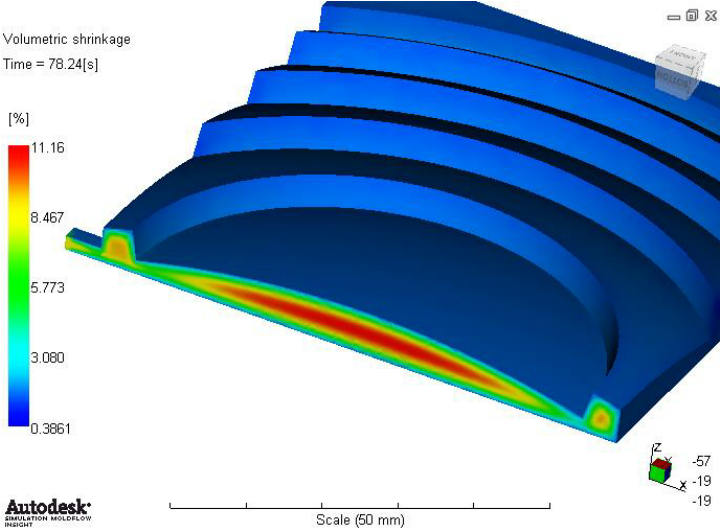
Image Credit: Research Gate
Mold Flow Analysis
For complex parts, one of the best ways to determine shrinkage is with a mold flow analysis. This software simulation shows how a plastic resin will fill an injection mold. A mold flow analysis can also help designers identify hard-to-fill mold locations.
The image below shows the shrinkage variation of an injection molded part. It’s from a simulation within Autodesk Moldflow, a commonly used software application for computer-aided engineering (CAE).
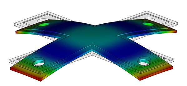
Image Credit: Plastics Technology
Typical Shrinkage Values
Table 4 below lists the shrinkage range (percentage) of some typical injection molding resins. Note that these values are a general range. For best results, refer to the datasheet for the injection molding material that you plan to use.
| Material | Shrinkage Range |
| ABS | 0.7–1.6 |
| PC/ABS | 0.5–0.7 |
| Acetal/POM (Delrin®) | 1.8–2.5 |
| ASA | 0.4–0.7 |
| HDPE | 1.5–4 |
| HIPS | 0.2–0.8 |
| LDPE | 2–4 |
| Nylon 6/6 | 0.7–3 |
| Nylon 6/6 Glass Filled (30%) | 0.5-0.5 |
| PBT | 0.5–2.2 |
| PBT Glass Filled (30%) | 0.2–1 |
| PEEK | 1.2–1.5 |
| PEEK Glass Filled (30%) | 0.4–0.8 |
| PEI (Ultem®) | 0.7–0.8 |
| PET | 0.2–3 |
| PMMA (Acrylic) | 0.2–0.8 |
| PC | 0.7-1 |
| PC Glass Filled (20–40%) | 0.1–0.5 |
| Polyethylene Glass Filled (30%) | 0.2–0.6 |
| Polypropylene Homopolymer | 1–3 |
| Polypropylene Copolymer | 2–3 |
| PPA | 1.5–2.2 |
| PPO | 0.5–0.7 |
| PPS | 0.6–1.4 |
| PPSU | 0.7-0.7 |
| Rigid PVC | 0.1–0.6 |
| SAN (AS) | 0.3–0.7 |
| TPE | 0.5–2.5 |
| TPU | 0.4–1.4 |
Table 4: Shrinkage Rates
Designers also need to consider that semi-crystalline resins have higher injection molding shrinkage rates than amorphous resins. The mold shrinkage chart in Figure 1 below illustrates this.
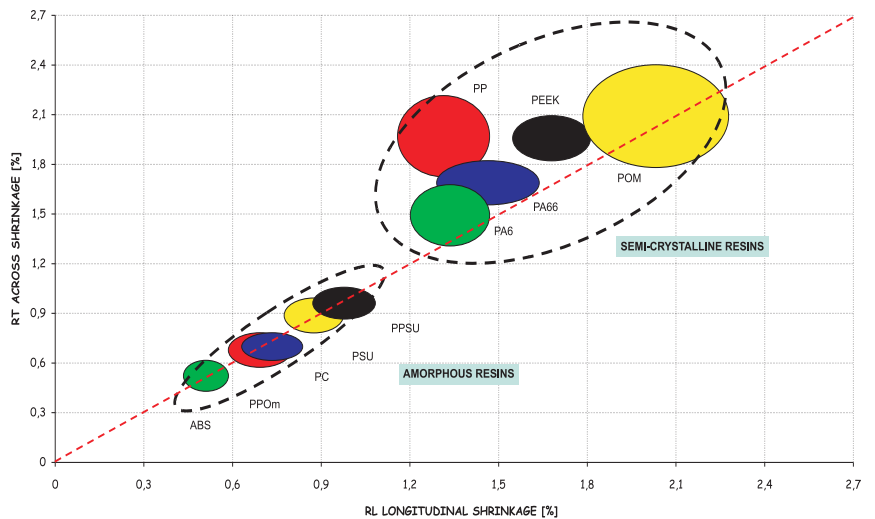
Figure 1: Semi-Crystalline vs. Amorphous ShrinkageImage Credit: The Tool Hub
How To Maintain Injection Molding Tolerances
To ensure your parts are injection molded with the tolerances you need, remember to account for the following factors.
Design For Manufacturability (DFM)
Following standard DFM principles is the best way to ensure that parts stay within defined tolerance parameters. Fictiv recommends referring to this free downloadable resource.
Download the Injection Molding Design Guide
Parting Line Mismatches
The dimensions measured across a parting line cannot be held to the same degree of precision as a feature that’s not bisected. If this is a factor in your part design, it’s essential to account for this mismatch.
Material Selection
Different injection molding materials shrink at different rates. Materials from different batches and suppliers can also have different shrinkage rates. Because long, fiber-reinforced polymers shrink less in the direction of the melt flow, expect asymmetrical shrinkage with these materials.
Process Control
Injection pressure, holding time, material density, and mold temperature all have a significant effect on a part’s overall shrinkage. By maintaining these parameters, an injection molder can ensure that parts have repeatable and predictable shrinkage.
FAQs about Injection Molding Tolerances
There’s plenty to consider when it comes to injection molding tolerances. The list below contains some frequently asked questions.
- Which injection molding tolerances must be specified?
- What are standard injection molding tolerances for parts?
- How does overall size and wall thickness affect part tolerance?
- Why is material selection so important for calculating shrinkage?
- How does tooling affect plastic injection molding tolerances?
- What’s the relationship between T1 tests and part tolerances?
- Where can you get help with plastic injection molding tolerances?
Which injection molding tolerances do you need to specify?
Commercial tolerances are less precise but less expensive to achieve. Fine tolerances are more precise but more expensive to achieve. Remember there isn’t just one type of dimensional tolerance you may need to specify on your part drawing.
Depending on your design, you may need to specify some or all of the following tolerance types.
- Dimensional
- Straightness/flatness
- Hole diameter
- Blind hole depth
- Concentricity/ovality
For flat parts like the plastic base for a medical device, you may need to specify a general tolerance and a flatness callout instead.
What are some standard injection molding tolerances for parts?
For non-critical applications like consumer products, injection molding tolerances are typically ±0.1 mm. For applications that require tighter tolerances, such as injection molded medical parts, ±0.025 mm is typical instead.
With assemblies of injection molded components, remember to consider how all parts fit together. This tolerance analysis, or tolerance stack up, must account for any interference, such as from a fastener head while providing adequate clearance.
How does overall size and wall thickness affect part tolerance?
Because larger injection molded parts experience more shrinkage, their dimensions are harder to control. Therefore, it’s harder to hold tighter tolerances for them in terms of overall part size and specific part features.
For injection molded parts of any size, maintaining a uniform wall thickness helps prevent uneven shrinkage. When a part’s wall sizes are non-uniform, the walls cool and shrink at different rates, which increases the risk of warping.
Why is material selection so important for calculating shrinkage?
Injection molding supports the use of many different materials, some of which are strengthened or modified with additives such as glass fillers and UV stabilizers. This broad material selection is attractive, but different plastics have different shrinkage rates. Moreover, these rates differ not just with the size of the overall part, but also with the inclusion of additives.
How does tooling affect plastic injection molding tolerances?
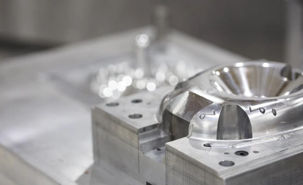
To maintain part tolerances, injection molds must provide consistent, repeatable heating and cooling. Mold makers need to place cooling channels with care and provide additional cooling for multi-cavity molds. When mold cavities are made from steel, such as with the tooling that Fictiv offers, the baseline for shrinkage calculations is more stable.
Out-of-tolerance molds result in out-of-tolerance parts. That’s why during the CNC machining of tools, mold makers must control tool dimensions. Typically, injection molds are machined to tolerances of ±0.127 mm. However, tight tolerances may require molds machined to ±0.0508 mm, while very tight molds are machined to ± 0.0254 mm.
Precision machining adds costs, so it’s essential to consider not only which tolerances are achievable, but also which ones are essential to your part design.
What’s the relationship between T1 tests and part tolerances?
T1 tests are the first part samples produced from the tool that will be used during production. These samples, which require your review and approval, demonstrate an injection mold’s ability to produce end-use parts.
T1 samples also provide an opportunity to check your drawing dimensions, especially critical dimensions for medical injection molding. Fictiv can deliver T1 samples (even for low-volume injection molding) in less than 14 days.
Where can you get help with plastic injection molding tolerances?
Fictiv makes it easy for part designers to get a quote in about 24 hours. Plus, every part that you upload to our platform is reviewed by experts and receives next-day DFM feedback. Fictiv’s manufacturing partners can support tight tolerances, and you’ll have real-time visibility of your injection molding project.
Sourcing Simplified – Start Your Next Project With Fictiv
For all your injection molding needs, Fictiv has you covered. Our injection molding experts are well-versed in managing shrinkage and maintaining tight tolerances. We can produce complex parts at amazing speeds and help you simplify sourcing with streamlined workflows.
Are you ready to get started? Create a free account and upload your part design today.
