Article contents
▸
Article
Team Fictiv
08.24.2021 Mechanical Design Tips
The information in this article is also available as a free e-book download.
Download the Injection Molding Design Guide
Injection molding is a fast and efficient way to produce plastic parts. The tool that it uses, an injection mold, has two main parts: the core and the cavity. These two halves of the mold come together, and molten plastic is injected into the tool.
Once the molten plastic cools, the two halves of the mold separate and the part is ejected. Depending on the construction of the mold and the part quantities that you need, this process can be repeated tens, hundreds, or many thousands of times.
That’s just a high-level overview, of course, but it lays the groundwork for the details you’ll find in this design guide. As you keep reading, remember that injection molding design is a three-part process.
This guide covers it all. Let’s get started.
Starting your part design comes with ten major considerations.
Injection molding materials range from commonly used polymers to specialty plastics and polymer blends. There are literally hundreds of different plastic resins available, and they each have different end-use properties and processing requirements. Plus, there can be different grades of the same plastic material, including resin types with glass fibers or carbon fibers.
| Resin | Characteristics |
| Acetal (POM) | Excellent rigidity and thermal stability with low water absorption and good chemical resistance |
| Acrylic (PMMA) | Strong, lightweight, shatter-resistant, optically clear, and UV and weather-resistant |
| Acrylonitrile Butadiene Styrene (ABS) | Strong and impact-resistant, even at low temperatures |
| Nylon (PA) | Tough with high heat resistance, high abrasion resistance, and good fatigue resistance |
| Polybutylene Terephthalate (PBT) | Resistant to creep and used in parts with thin cross-sections |
| Polycarbonate (PC) | Strong, lightweight, and naturally transparent, with stable properties over a wide temperature range |
| Polyether Ether Ketone (PEEK) | Excellent mechanical properties and resistance to chemicals and thermal degradation |
| Polyetherimide (PEI) | Combines stiffness and stability with low flammability and low smoke production |
| Polyethylene (PE) | Generally used for indoor applications. Chemically resistant. Includes high and low-density materials. |
| Polyphenylsulfone (PPSU) | High toughness, high flexural and tensile strength, and good resistance to chemicals and heat |
| Polypropylene (PP) | Good chemical resistance and won’t degrade when exposed to moisture or water |
| Polystyrene (PS) | Lightweight, relatively inexpensive, and resistant to moisture and bacterial growth |
| Thermoplastic Elastomer (TPE) | Processed like plastic but has the properties and performance of rubber |
| Thermoplastic Polyurethane (TPU) | Rubber-like elasticity with good load-bearing capabilities |
Wall thickness affects the strength, cost, and appearance of your injected molded part. Simply put, it’s one of the most important design considerations.
There are three wall thickness terms that designers need to understand:
Whenever possible, apply a uniform wall thickness to your part. This best practice promotes more consistent cooling and, consequently, more consistent shrinking.
You can use walls with different thicknesses, but they’ll cool and shrink at different rates. This may cause sink, warp, and other injection molding defects.
Nominal wall thickness is the thickness throughout your part. A uniform wall thickness is recommended, but it’s also important to avoid walls that are too thick or too thin.
In addition, keep wall thickness (or thicknesses) within range for the plastic material you’ve selected. The next section lists the recommended wall thicknesses for common plastic resins.
| Resin | in | mm |
| Acetal (POM) | 0.030–0.120 | 0.76–3.05 |
| Acrylic (PMMA) | 0.025–0.150 | 0.025–0.150 |
| Acrylonitrile butadienestyrene (ABS) | 0.045–0.140 | 1.14–3.56 |
| Nylon (PA) | 0.030–0.115 | 0.76–2.92 |
| Polybutylene Terephthalate(PBT) | 0.080-0.250 | 2.032-6.350 |
| Polycarbonate (PC) | 0.040–0.150 | 1.02–3.81 |
| Polyether Ether Ketone (PEEK) | 0.020-0.200 | 0.508-5.080 |
| Polyetherimide (PEI) | 0.080-0.120 | 2.032-3.048 |
| Polyethylene (PE) | 0.030–0.200 | 0.76–5.08 |
| Polyphenylsulphone (PPSU) | 0.030-0.250 | 0.762-6.350 |
| Polypropylene (PP) | 0.040–0.150 | 1.02–3.81 |
| Polystyrene (PS) | 0.025–0.125 | 0.64–3.18 |
| Thermoplastic Elastomer(TPE) | 0.025–0.125 | 0.64–3.18 |
| Thermoplastic Polyurethane (TPU) | 0.025–0.125 | 0.64–3.18 |
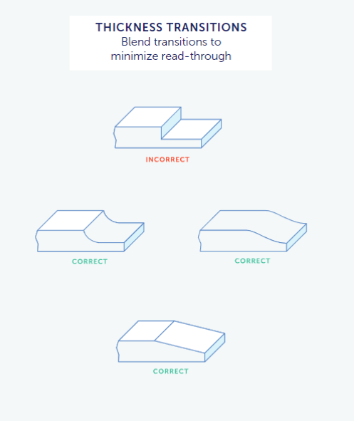
If you can’t maintain a uniform wall thickness throughout your design, use smooth transitions between sections with different thicknesses.
Best practice is to smooth, or blend, transitions between areas with different wall thicknesses to minimize stress concentrations that can result in part failure.
There are two main ways to achieve these transitions: chamfers and fillets.
Smooth transitions aren’t the only way to avoid stress concentrations, however. Using rounded corners instead of sharp ones can help.
Sharp edges don’t just concentrate stresses. They also increase part costs because they require molds that are made with electrical discharge machining (EDM).
Sharp corners are a good place for parting lines, as we’ll see later in this guide, but it’s best to use them wisely and, where possible, use rounded corners instead.
Rounded corners limit stress concentrations and minimize differences in shrinkage as the plastic material cools. They also help to control tooling costs and enable the molten plastic to flow more readily throughout the mold.
When you apply rounded corners to your part design, follow these guidelines:
Draft is an angle you apply to vertical walls so that parts will eject cleanly from the mold. This taper can also decrease tool wear and reduce cooling times, both of which help to control costs.
When specifying the amount of draft to apply, consider the following.
Draft angles vary by the type of resin, or injection molding material. There are also different systems, or standards, that define the amount of draft to apply.
Trade associations and companies define standards and designations for injection molding finishes, which include textures and polishes.
This is why you’ll hear terms like “SPI finishes” and “Mold Tech textures” during DFM discussions.
Draft is related to the texture of your injection molded parts. During injection molding, the texture that you want is transferred from the mold to part surfaces.
Smoother finishes require less draft and finishes with heavier textures require more draft.
In general, it’s best to add 1.5° of draft per 0.001” or 0.025 mm of textured depth. SPI, VDI, MT, and YS publish tables with recommended draft angles.
Polish isn’t a function of draft, but it’s worth mentioning here because — as with texture — the finish for your part is imparted by the finish of your mold.
Finally, remember to set the draft angle based on the mold’s draw, or how it separates. Otherwise, the part may not stay in, or stick to, the half of the mold that contains the ejector
system. Consider both the draft on the part’s vertical walls and on part features.
For example, in the case of a rectangular part with four through-holes, drafting the holes toward the cavity could cause parts to stick there instead of to the core. A better approach would be to draft the holes toward the core where the ejector system is located.
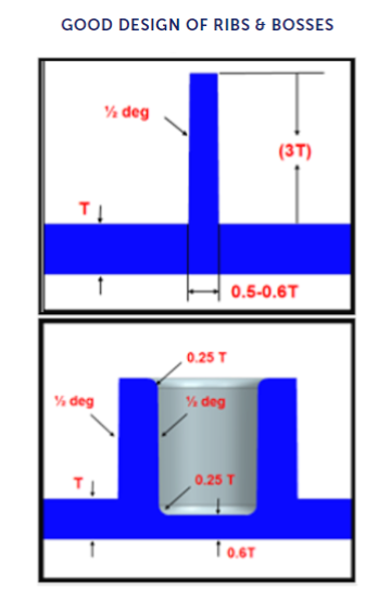
Injection molded parts have thin walls to support faster production speeds and longer mold life. Yet thin-walled parts may lack sufficient strength. Ribs and bosses increase part strength, but there are some key rules to follow when adding them to your design.
Ribs are vertical features that add structural integrity and increase load-bearing capacity.
Thick ribs are prone to shrinkage, however, as this chart shows.
If a rib is too thick, sink marks may appear on its opposite side and mar the part’s finish.
To avoid these problems, follow these best practices:
Bosses are vertical features that support assembly and increase a part’s structural integrity. They can accommodate fasteners such as screws and, as with dowel pins, smaller bosses can be inserted into larger bosses within walls.
When designing bosses, remember the following:
Injection-molded parts that are used in larger assemblies need to have correct and consistent dimensions. Because some degree of dimensional deviation is expected in any process, designers need to define a part’s acceptable dimensional variations or tolerances.
There are two main types of injection molding tolerances.
Like wall thickness and draft, dimensional tolerances vary by resin. There are also different tolerances for overall sizing and for specific part features.
For mating parts, consider the tolerance stack-up as well. This refers to how all of the components in an assembly, and their individual tolerances, must fit together.
For example, an assembly has three parts, each with a screw hole. The hole in each part is within tolerance, but the holes must align so the screw can pass through all of them.
Injection molds have a parting line where the tool opens and closes. Sometimes, the parting line is right down the middle of the injected molded part. That’s usually what designers think of when they envision a parting line, but that’s not always the case – or even a best practice.
Take, for example, a LEGO® brick. The parting line is not down the top-middle of the brick, where it would be very noticeable. Rather, the parting line is along the brick’s bottom edges so that you have to turn over the brick to see it.
Sharp edges concentrate stresses but they’re a good place for parting lines because they simplify mold construction, which helps to reduce project costs. Avoid filleted surfaces, however,
because they don’t work well with parting lines:
Gates are openings in an injection mold that allow molten plastic to enter the cavity.
Designers also need to consider gate location because gates leave plastic protruding from the part’s surface. This extra plastic gets trimmed, but it’s best to put gates where any small marks that are left behind are least noticeable. Often, gates are placed along the mold’s parting line.
Trimming provides a way to categorize gates, but specific types of gates are recommended for parts with specific part features. Some gates require manual trimming. Others support automatic trimming where excess material is sheared during part ejection.
Ejector pins are used to eject a part from a mold after cooling is complete. Sometimes, however, the mold sticks, which causes marks from the ejector pins to appear on the finished part.
For best results, locate ejector pins on part surfaces that are not visible. There are other guidelines to consider as well — some are a function of the mold-making process, but part designers need to understand them in order to evaluate tooling.
Now that you’ve started your part design and defined some key characteristics, it’s time to upload your design and get expert DFM feedback from Fictiv.
Fictiv provides DFM feedback along with your request for a quote. Just create a free Fictiv account, upload your CAD file, and then review and incorporate the feedback using the 3D visualization tool built-in to the Fictiv platform.
Most manufacturers won’t provide DFM feedback until you place an order, but Fictiv provides a full DFM analysis for free along with your quote. At this stage, the aim is to discover all of the potential issues or risks for mold making and injection molding.
Here are a few common DFM questions that Fictiv’s engineers will answer when you work with us:
The DFM stage is critical because when your part is still being designed, small modifications typically take just a few minutes or hours to complete. After your tooling is cut, however, it can take at least a few days and hundreds of dollars just to make a small tooling change.
By working with Fictiv and incorporating the expert DFM feedback that you receive from us, you’ll be ready for mold-making and part sampling. You’ll also get access to a highly-vetted network of local and overseas injection molders, as well as a dedicated U.S. service team.
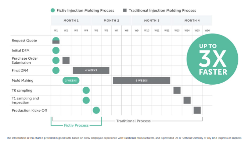
During Step 1 of the injection molding design process, you’ll consider how the injection mold that will be used to produce your parts can affect part costs and quality. During Step 2, Fictiv reviews your design for manufacturability.
In the final step of the injection molding design process, a tool maker will create your mold and an injection molder will send you part samples. Because your part design may change based on the trial samples that you receive, there are a few more steps to consider.
A. Mold Making
B. Sample Parts
C. Begin Production
After you submit your part design for tooling, a mold maker will cut the steel or aluminum that’s used for the core and cavity. Bench workers will then assemble the mold, incorporate off-the-shelf parts such as ejector pins, and test the mold for leaks.
For new product introduction (NPI), Fictiv recommends starting with a single-cavity tool because these molds are less expensive to make and take less time to produce. That’s important since your design may change and require new tooling.
When your design is truly final, you can ramp up production by ordering multi-cavity molds or family molds that combine different part numbers into the same mold base.
Use the sample parts that you receive to perform functional testing and dimensional measurements. Expect your samples to be within the tolerances you’ve specified and very close to meeting all of your requirements.
If your part design included a textured finish, your sample parts will include this as well. There are hundreds of texture options, so make sure the light, medium, or heavy texture you’ve received is satisfactory.
If your sample parts require adjustments, submit an engineering change order. For example, you might need to tighten up some tolerances. Then, when you’re satisfied with your samples, it’s time for production.
After you’ve approved your part samples, injection molding production can begin. Depending on the tool’s construction, you can get tens, hundreds, or many thousands of parts.
Because Fictiv doesn’t have minimum order quantities (MOQs), remember that you can ramp up production gradually to match customer demand.
As you’ve learned from this guide, there’s much to consider when designing injection molded parts. But don’t worry! Partnering with Fictiv means that we’ll shoulder the heaviest parts of the burden. Count on our guided expertise to improve your design and ensure a successful product launch.
Create your free Fictiv account and upload your part drawing at fictiv.com/signup
High quality tooling, done your way.
LEAD TIME | T1 samples as fast as 10 days
QUALITY ASSURANCE
TOOLING TYPES & FINISHES | Types: Single Cavity, Multi-Cavity, Family Tooling. Finishes: Glossy, Semi-Glossy, Matte, Textured
TOOLING MATERIALS | P20 Steel, NAK80 Steel, H13 Steel, Stainless Steel, Aluminum
SECONDARY OPERATIONS | Pad Printing, Silkscreen Printing, Painting, Laser Etching, Ultrasonic Welding, Insert Heat Staking, Insert Molding
GEOGRAPHIES | U.S. & overseas options available
INJECTION MOLDING MATERIALS | All commercially available materials + custom materials
PRESS SIZES | 50-3,300 ton machine presses
By signing up, you agree to our Terms of Use and Privacy Policy. We may use the info you submit to contact you and use data from third parties to personalize your experience.


