Time to read: 6 min
Geometric Dimensioning and Tolerancing (GD&T) is the building block of modern engineering drawings. To learn the basics of GD&T, check out our GD&T 101 article which includes the definitions and utilization of:
- CNC machining tolerances
- The Datum Reference Frame (DRF)
- Interpreting GD&T Symbols
- Applying Geometric Symbols to Engineering Drawings
- The Feature Control Frame
- Communicating Basic Dimensions
- Material Condition Modifiers
Now let’s put theory to practice and actually step through the GD&T process.
Step One: Setting up the Datum Reference Frame
Defining the datum reference frame is the first step to ensuring you have a drawing with proper GD&T. The datum reference frame consists of primary, secondary, and tertiary datums. The purpose of the datum reference frame is to restrict your component by fixing it with respect to the six degrees of freedom: X translation, Y translation, Z translation, X rotation, Y rotation, and Z rotation. The three datums should be mutually perpendicular to each other and selected in an order of precedence according to the following requirements:
- Primary Datum should be selected on a plane that contains features that are critical to the function and/or inspection of the feature (think mating surface). It must have at least three points of contact with the part which are not in a straight line (a plane).
- Secondary Datum should be perpendicular to the primary datum and have a minimum of two points of contact (a line). This datum often establishes the orientation of the second axis.
- Tertiary Datum should be perpendicular to both the primary and secondary datums and must only form one point of contact (a point). The third datum feature contacts the third plane of the datum reference framework.
Datums should be selected in order of importance, depending on characteristics such as mating surfaces, easy-to-see surfaces, functional part surfaces, and surfaces with a large enough surface area to allow for measurements during inspection. Datum features must be distinguishably different features of a part. So, if a part is mirrored and a datum feature would have two identical possible locations, the datum feature must be identified on the part.
Pro-tip: Datums should be chosen with inspection in mind and should allow for measurements to be taken with respect to them — so they should be in tangible, accessible locations.
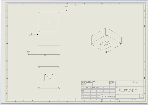
For the purposes of this how-to-guide for GD&T, we will utilize the following solid model which shows a CNC machined block with holes. See Figure 1 for the selection of the datums.
Datum A, the Primary Datum, was chosen because it is the primary mating surface on the component, sets the orientation of the part, and the bolt holes are perpendicular to its surface. Remember, a primary datum should be chosen with the location of the critical feature in mind. Also, you should always consider how a part will be dimensioned prior to defining the datums.
Datum B, the Secondary Datum, is perpendicular to the Primary Datum and sets the orientation of the second axis. Datum C, the Tertiary Datum, is perpendicular to the other datums and fixes the degrees of freedom of the part. Now we can dimension features off the three datums, providing reference points for dimensions in each direction.

Pro-tip: While we are using SOLIDWORKS 2022 for this step-by-step GD&T guide, you can follow along with any drafting software!
Step Two: Dimension Your Drawing
I like to start out by defining the most critical dimensions and tolerances that relate to fit, form, and function. Defining these dimensions and tolerances first gets me into a practice of thinking of the most important features so I can think of how to apply geometric tolerances. This often means first determining what the major mating surfaces are and whether they are classified as clearance, interference, or transition fits. The first rule when beginning to define geometric dimensions and tolerances is that all dimensions must have a tolerance. Why? Because all physical objects are imperfect and have variations or imperfections. So, in order to control these variations, we must define their limits as tolerances.
All dimensions are also based on the datum reference framework as a type of coordinate system. Dimensions can be one of the following forms:
- Reference Dimension: Features that have reference dimensions are for reference only, for visualization purposes. A reference dimension is called out on a drawing with parenthesis — i.e. (0.525) — and these dimensions are not inspected.
- Tolerance Dimension: Tolerance dimensions have tolerances without the rules of GD&T applied to them. They are typically represented with a ± symbol and a numerical tolerance value, or a lower and upper limit.
- Basic dimensions: Basic dimensions are those we apply the GD&T rules to. This is where you apply tolerances and theoretical dimensional limits with GD&T because they have some variation and can’t be precisely correct. Basic dimensions are placed in boxes and are typically used in conjunction with the location or geometry of feature control within the GD&T framework.
The below example is not fully dimensioned for illustration and clarity purposes, but it shows how to correctly apply reference, tolerance, and basic dimensions:

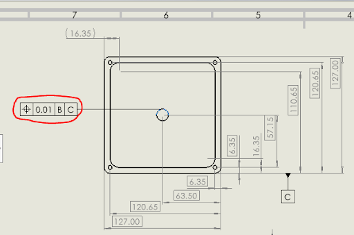
The goal of dimensioning a part is to ensure that every feature can be manufactured with the information provided. Any additional dimensions beyond what is required to inspect or manufacture the part should be marked as a reference dimension. As we can see from Figure 2, this part cannot be machined with the provided dimensions. For example, we don’t know the hole diameters or the radii for the filleted edges, among other dimensions.
Another rule for applying dimensions to a drawing is to only apply them to visible drawing lines and ensure they’re legible. I try to utilize even spacing of dimensions and have them flow in a logical order, without overlapping dimension markers wherever possible.
Pro-tip: Walk through the manufacturing processes of your part to ensure you have captured all required dimensions. It’s also good practice to have someone else check your work!
Step Three: Apply Geometric Tolerances (GD&T Tolerance)
Geometric tolerances are defined using feature control frames, and there are over twenty GD&T symbols. For a refresher on how to utilize these symbols, check out our GD&T 101 article or our on-demand GD&T webinar. Note that each part typically has multiple features to which geometric tolerances should be applied, and any given feature can have multiple geometric features.
When applying geometric tolerances to geometric features, consider the function of the geometric feature at hand. For example, Figure 3 shows just one geometric tolerance of the center hole in our example part. This hole has a mating rod that attaches to this part, so its position with respect to datums B and C is critical for this assembly to function properly. So, you can see the true position geometric tolerance has been applied with respect to the secondary and tertiary datums B and C, respectively.

It’s also important to remember that the geometric features of a component are related to each other and tighter geometric tolerances result in higher costs.
Also, note that geometric tolerances are not meant to replace dimensional tolerances, but to complement dimensional tolerances. Always ensure that the key characteristics of the part’s orientation, fit, form, and function are clearly defined with geometric tolerances.
Pro-tip: Review basic GD&T rules with this excellent (and free) resource.
Step Four: Quality Check and Tolerance Analysis
As a general rule, you should always have a second set of eyes check your engineering drawings. You may think your drawing is well defined, with easily understood and measurable defined dimensions, tolerances, and geometric constraints. However, this may not always be the case. Personally, I enjoy the challenge of getting a 20-page-long drawing packet with the goal of fixing any errors present! So, spread the love to your coworkers — we all know engineers love finding and fixing each other’s mistakes 😂.
Also, you should perform a tolerance analysis to figure out the overall deviation (and its impact on your parts) that stems from any imperfections in the manufacturing process. There are many methods and tools for performing a tolerance analysis, whether it’s a pen and paper, an Excel spreadsheet, specialized software, or 2022 CAD tools. The benefits of performing a tolerance analysis include: reducing part-to-part variation, optimizing production processes, improving part quality, and controlling rework/scrap.
Start Your Next Project With Fictiv
If you’re tasked with sourcing and supplying mechanical parts, Fictiv is your operating system for custom manufacturing that makes part procurement faster, easier, and more efficient. In other words, Fictiv lets engineers, like you, engineer.
With our design and manufacturing expertise and an innovative platform that provides instant DFM feedback, complete production visibility, and quick turnaround times, manufacturing your parts is easier than ever!


