Time to read: 7 min
When designing a product, it’s important to base your design on the manufacturing process you intend to use. It helps to consider this as early as possible in the design process, as it can be more time-consuming to go back and add manufacturing details later once the design is further along.
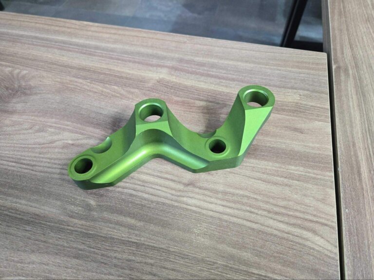
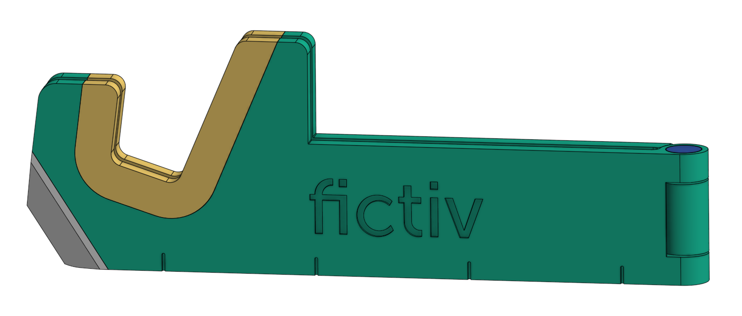
In the case of this multi-tool phone stand, I wanted to make something that could be prototyped with 3D-printing or CNC machining, but with the end goal of injection molding the final product. This design goes through a similar DFM (design for manufacturing) process as typical molded parts, with the additional complexity of overmolding.
In this second article segment of the Fictiv-Made series, we’ll chronicle the detailed design phase for injection molding and cover DFM requirements, over-molding, and insert molding.
Design for Injection Molding
Wall Thickness
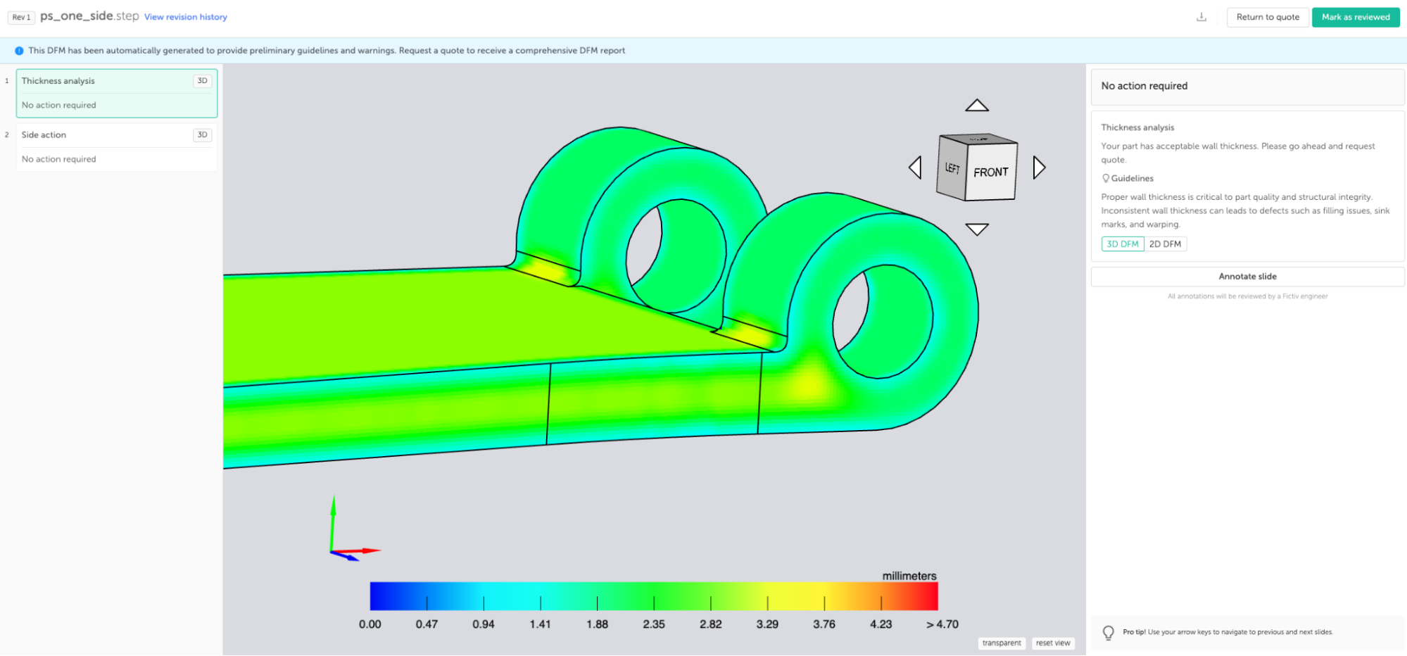
One of the most essential factors in injection molding is wall thickness. It’s critical to keep the thickness as consistent as possible and core the part out as necessary. Because of this, it helps to think about what the thickness should be and whether it needs to be shelled out up front.
A good rule of thumb for the nominal wall thickness of an injection-molded part is 1-5 mm (0.04-0.20 in). It is also beneficial to reference similar molded parts currently available in the market. While minor thickness variations throughout the part are acceptable, significant thickness variations can lead to defects such as sink marks.
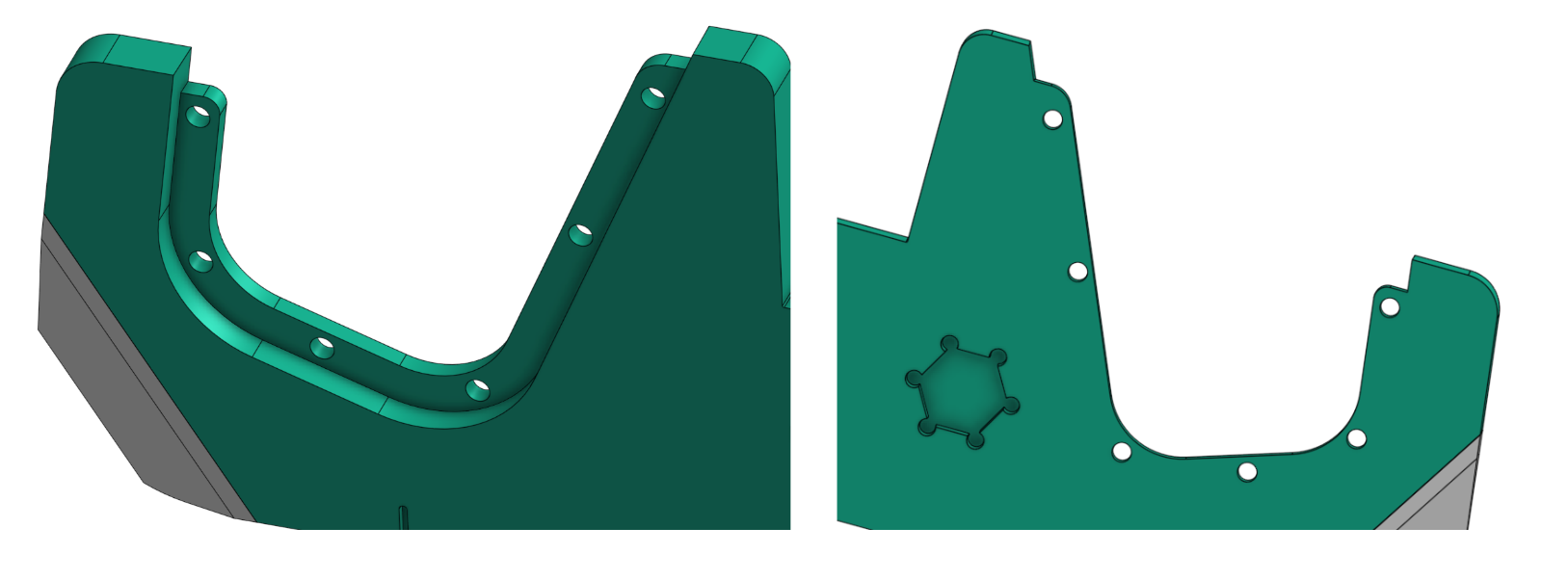
Since these parts are generally flat and of uniform thickness, coring out and shelling the model was not a concern for this project. However, in a few areas of the design, it was important to keep a consistent thickness. The hinge area had to be cored out to fit the hinge pin while leaving enough material to fill and secure the pin structurally.
The overall thickness of the flat parts and the material choice are also critical because they drive the stiffness and pocketability of the product. This is best determined and tested as early in the process as possible to avoid affecting the overall design later by adding other stiffening features, such as ribs, that are not ideal cosmetically.
Draft Angle
Draft is a critical feature in injection-molded parts that ensures the part can be removed from the tool without defects. A proper draft angle on the part’s surfaces will allow easy removal without deformation, scratching, or drag marks.
Draft is also important to consider and build into the model early on, as it may affect the overall form and function of the product. In this case, flat areas in the hinge area were mating surfaces, so the draft direction and angle had to be selected accordingly to maintain clearances with tolerance, and functionality in rotation.
Often, in product development, designers push for a smaller draft angle and manufacturers request a larger one to ensure quality and output. This is an important back-and-forth that must be resolved during the DFM phase.
A general rule of thumb for draft is 1-5 degrees, but it can depend more or less on the draw distance and the surface finish. A heavier texture requires more draft, while with a polished surface, you can get away with minimal or even zero draft.
Slides
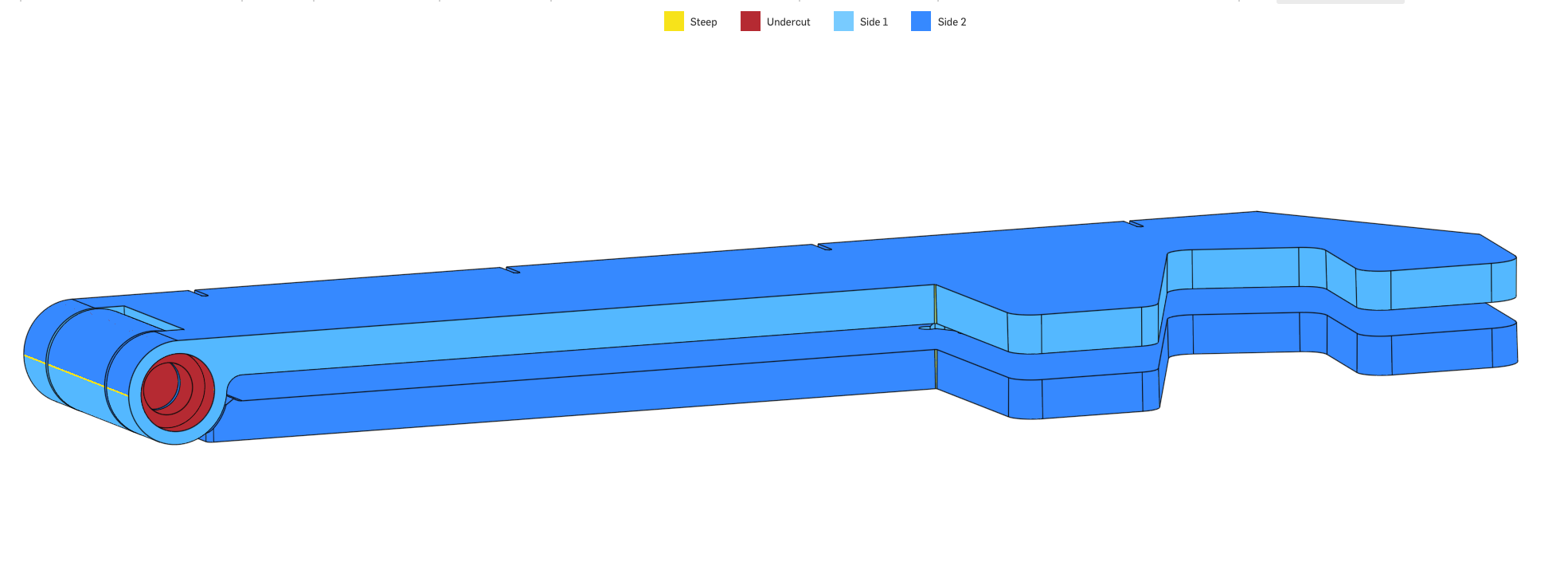
Slides are parts of the tool that pull in a different direction from the core and cavity (A and B sides). They can achieve undercuts like those shown in the hinge area below. They typically require draft as well, but not always with circular pins.
Radii and Fillets
Rounds are essential for injection-molded parts, and sharp corners are not ideal. Radii (external corners) and fillets (internal corners) ensure proper material flow, part strength, and easier removal from the tool.
For additional tips on DFM for injection molding, download and view our injection molding design guide.
Design For Overmolding
Overmolding is an excellent benefit of injection molding that allows parts to be made of multiple materials. It enhances product functionality in sealing or drop protection, as well as aesthetic improvements and color breaks.
Manual (Pick-and-Place) Overmolding
Insert molding or overmolding is when a part made from one material in one mold is placed into another tool, and another material is injected and molded over it. The parts are then combined into one with a combination of mechanical and chemical bonding. Different materials can be insert-molded, but the most common are plastic and metal. The second-shot material is usually another plastic, or a rubber-like material such as TPE or TPU.
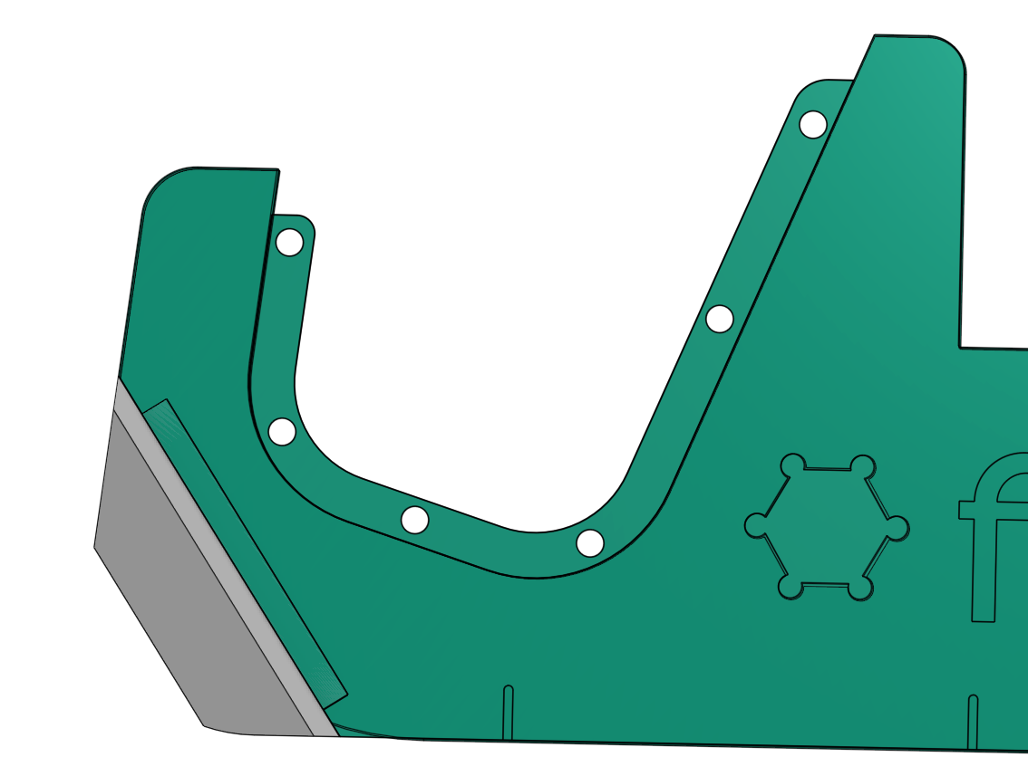
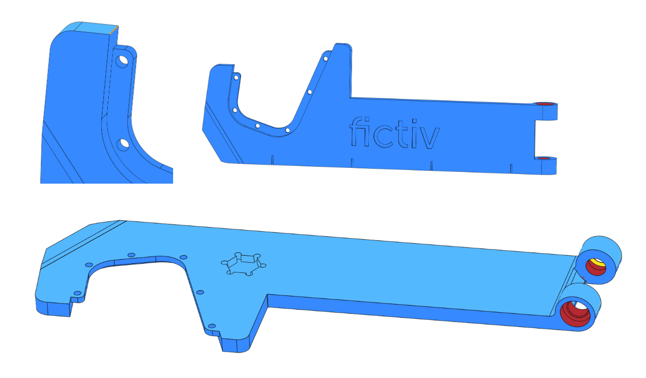
This multi-tool phone stand product combines multiple materials to add improved functionality for securely holding the phone and the box cutter feature. In the design shown in the section below, a metal part is insert-molded with a plastic part that is then overmolded with TPU.
Retention Features
With any type of overmolding, the bond is critical to prevent delamination or peeling of the overmold and substrate. It’s essential to increase the surface area where the bond is made as much as possible. Bonding can also be improved with proper injection molding parameters that can be adjusted.
One way to gain more surface area is to create retention features, such as ribs, steps, and through-holes. Below are three options for mechanical retention, with an assessment of their pros and cons.
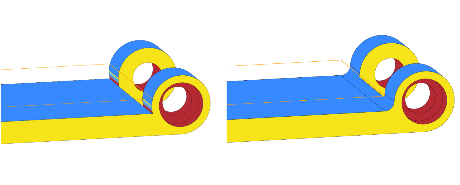
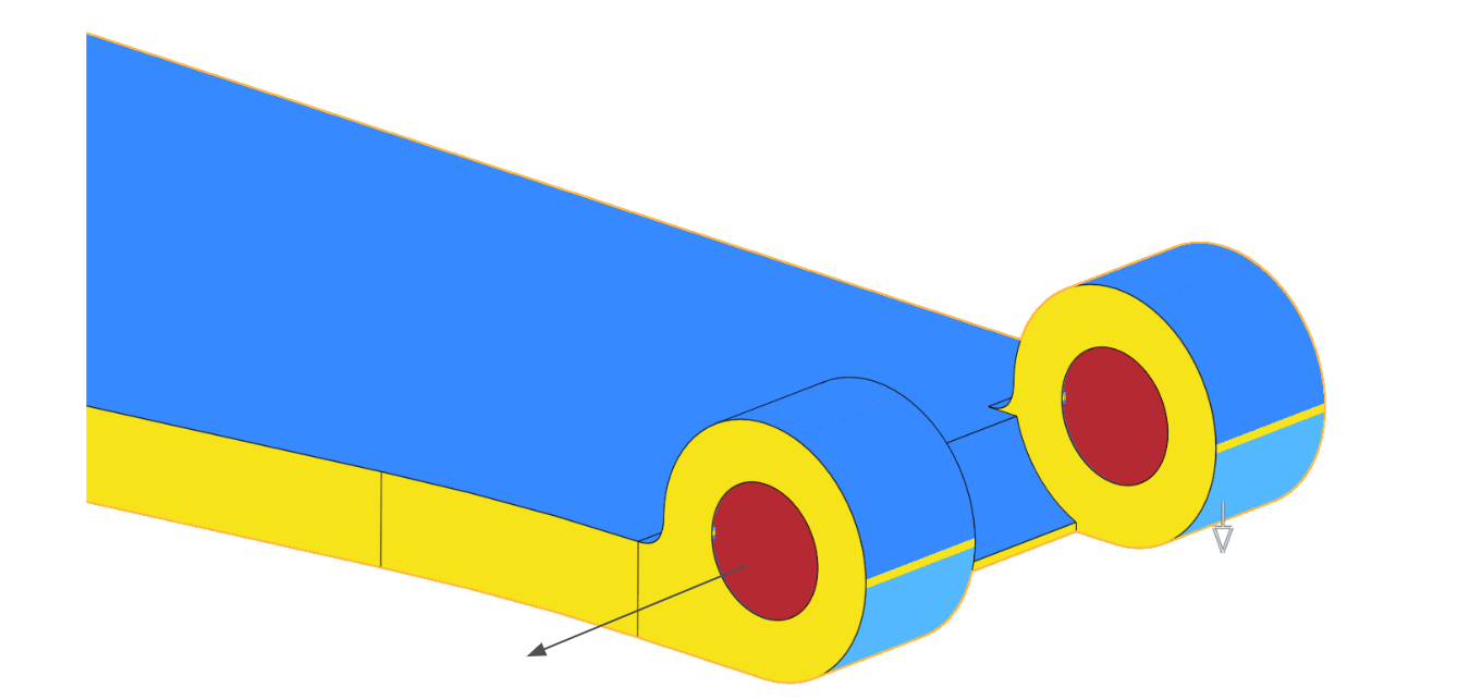
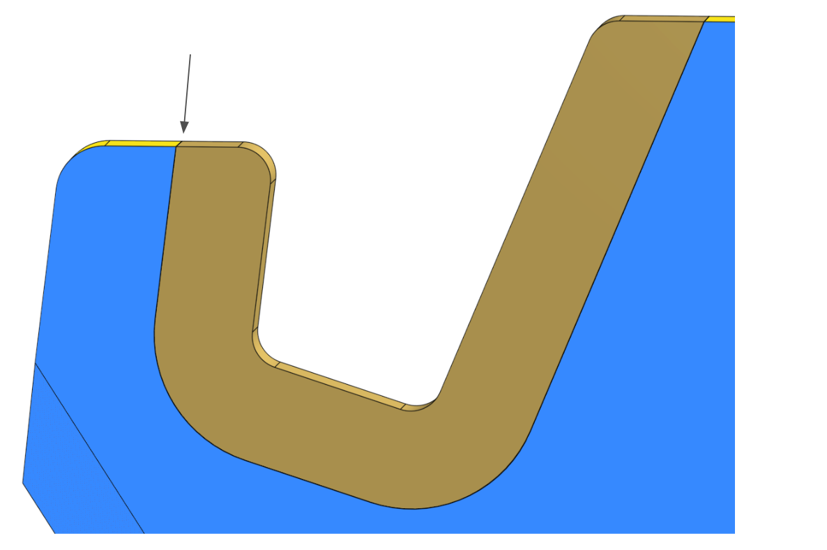
A mid-plane rib in this area allows excellent bonding with TPU material for the second shot on both sides. The challenge arises that an undercut is created in the pull direction of the overall part. Drafting it in the direction of a slide pull can solve that, but the rib becomes too thin in one area. It also creates unnecessary tool complexity, meaning a higher cost. You could split the draft at the mid-point of the rib, but it generates a parting line on the side of the part that’s not ideal cosmetically.
Holes in the rib significantly improve retention by increasing surface area even more, and the TPU that fills them creates a mechanical interlock with the substrate to prevent delamination. However, these holes must be pulled in the draft direction of the overall part.
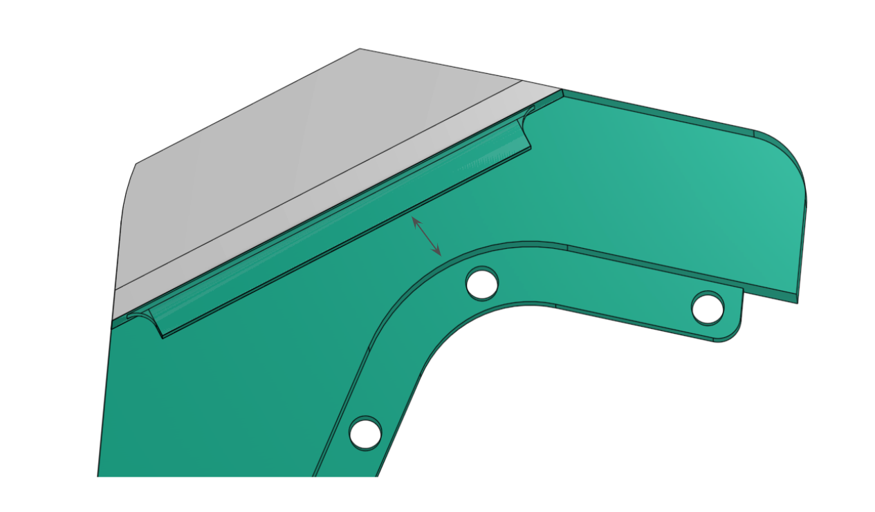
Moving the rib to the parting line (surface where the draft starts), will solve the undercut issue. It decreases the surface area of the bond between the materials compared to the previous option, but still improves it. Through-holes can then be added as well. With this solution, the rib and holes will be visible on one side of the part—but in this case, it’s the interior side, where they won’t be seen when the part is in a collapsed state.
The rib, being on the interior side, drives the parting line and draft direction. In this case, the overall draft for the part had to be flipped to prevent a jogged parting line.
It’s also important to avoid sharp or thin sections of the substrate. Sharp corners more easily create delamination and propagate peeling than soft or square corners.
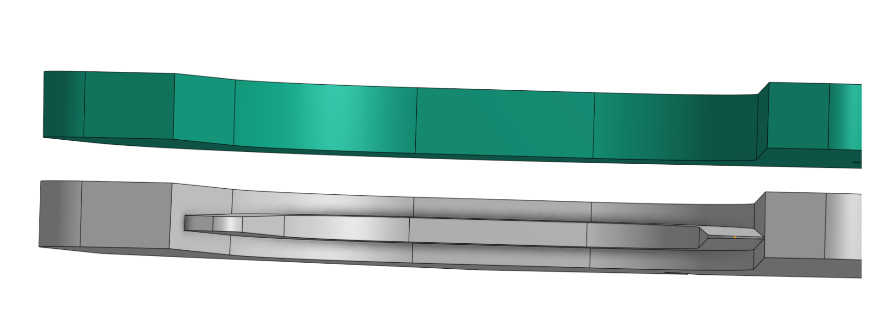
Metal Insert Molding
The same bonding principles apply to metal insert molding, but can be more difficult due to differences in material properties and the increased heat difference with metal parts.
Material thickness and flow must be considered in this case, so there is enough space for the overmolded material to flow and fill around the metal blade part properly.
Multi-Shot Overmolding:
Multi-shot overmolding differs from manual overmolding in that the subsequent shots occur within the same tooling cycle as the original substrate part. This method offers advantages over manual pick-and-place molding, such as reduced cycle time and lower costs. However, it does require a higher upfront investment in tooling and manufacturers who have experience with the process.
The multi-tool phone stand product used as an example in this article is a great candidate for multi-shot molding. The differences between two-shot and three-shot molding are described below:
Two-Shot (2K) Overmolding
Two-shot, or 2K overmolding, is a process in which two different materials are injected sequentially into the same mold during a single molding cycle. This eliminates the need for manual substrate placement, improving part alignment, reducing cycle time, and increasing overall efficiency.
Advantages of 2K overmolding:
- Stronger bond between materials due to in-mold sequence
- No secondary handling or alignment needed
- High repeatability and lower labor costs
- Clean parting lines and superior cosmetic results
Three-Shot (3K) Overmolding
Three-shot overmolding (or 3K molding) extends the 2K concept by introducing a third material into the mold sequence. This process is used when a part requires multiple functional or aesthetic materials, such as a rigid frame, a soft grip, and a clear window or logo overlay—all molded in a single cycle.
While less common than 2K due to higher tooling and machine complexity, 3K molding offers unparalleled part integration and design freedom, especially in high-volume applications where product differentiation and performance are key.
Use cases include:
- Multi-color branding and UI zones
- Combining rigid, flexible, and transparent materials
- Sealed enclosures with soft-touch buttons and rigid internals
Multi-Shot Molding with Fictiv
Fictiv’s global manufacturing network includes partners experienced in 2K molding, making it easy to source complex multi-material parts with short lead times and optimized costs.
3K molding requires highly specialized equipment and tooling, but Fictiv’s vetted network of manufacturing partners ensures access to this advanced capability without the typical overhead of sourcing and qualification. This enables teams to push product innovation without compromising scalability or cost control.
Fictiv-Made Design Process
Stay tuned for more of the Fictiv-Made series as we document the full journey of this multi-tool phone stand from initial concept sketches to prototyping, DFM iterations, and final production-ready parts.
At Fictiv, we’re more than just a manufacturing platform — we’re your supply chain partner, helping innovative teams navigate uncertainty, accelerate development cycles, and scale confidently from prototype to production with high-quality parts, fast.
If you’re ready to bring your next product to life, sign up or log in to upload your design files and get an instant quote today. Let’s build something great together.