Time to read: 5 min
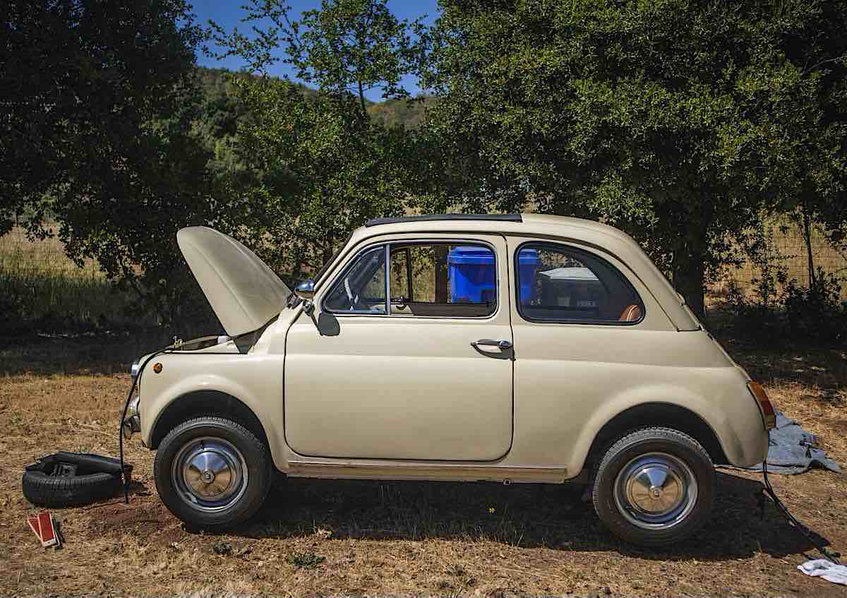
Welcome to the next installment of our Butterball EV conversion! In case you didn’t read our introductory article, Butterball is our pet name for the cream-colored 1966 Fiat 500 that we converted to an electric vehicle this past year as a means to foster community here at Fictiv while we were all working remotely.
You can read more about the electrical design and prototyping phases of the project, too!
Modeling the Existing Car
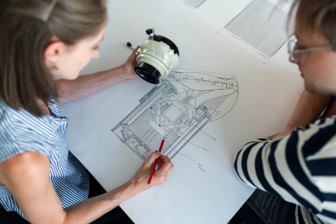
The mechanical design was a significant aspect of this project. It began with modeling the internal spaces of the car. This was essential to be able to plan the layout of important components — like the motor and battery boxes — and to determine where and how these components would be mounted.
The modeling step first required detailed measurements of all spaces and existing components. The spaces had to be measured by hand. Because this car is so old, documentation is not available or easy to find. Luckily, we had someone on our team (shoutout to Veda!) with great attention to detail to collect detailed measurements. Those measurements let us model the trunk and frunk (front trunk) of the car in OnShape, a handy online CAD platform, using its sheet metal functionality.
Modeling the EV Components
Next, the other components had to be modeled. Some of the modern components, like the motor and batteries, were easier to model because they had existing CAD files that we could use. Additionally, we knew the batteries would be mounted within boxes, so they were simple to model in CAD.
The bell housing plate for the motor, however, was quite difficult to model. The bell housing is part of the transmission that covers the flywheel and clutch of the original car’s drivetrain. One set of holes on the plate was fastened to the mounting holes on the motor, while another set of holes was fastened to the bell housing.
Because we couldn’t find documentation for the car, we had to measure the specific hole pattern on the bell housing by hand. First, we tried shading the holes on a piece of paper that we laid on the bell housing with a pencil to make a tracing of the holes. Then we took pictures of the bell housing, measured the number of pixels, and equated those values to inches to find the measurements. In the end, those efforts combined with oversizing the holes for extra clearance were sufficient to create a bell housing plate model.
Designing the Component Layout
With the spaces and parts modeled out, the next step was to figure out the layout of the components within the car. This was no easy feat; if you’ve seen an old Fiat 500 from the ‘60s, you know they’re tiny cars!

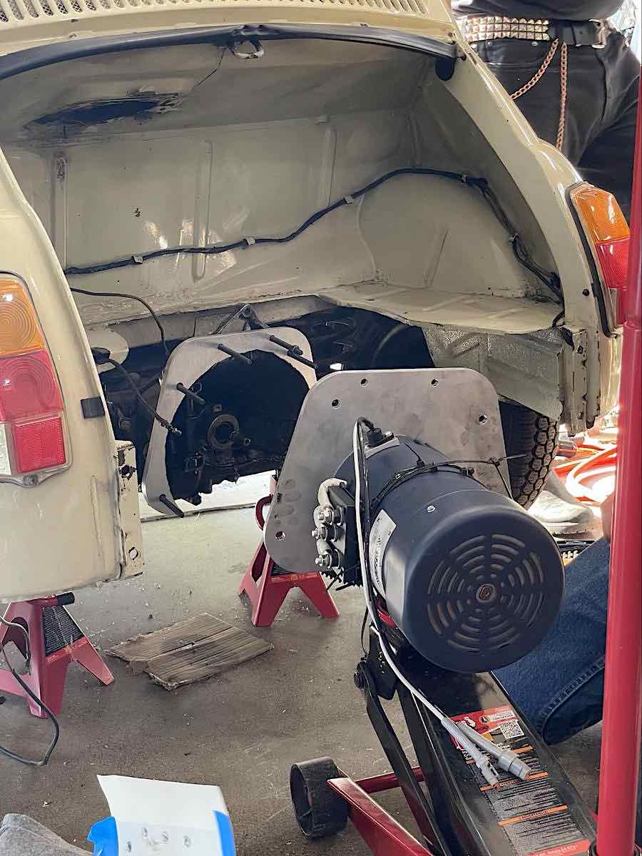
Getting back to the layout, the assembly feature in OnShape was useful in determining the orientation of the parts. However, it’s important to remember that just because you can do something in CAD doesn’t mean that it will be easy, or even possible, in real life. We were reminded of this lesson the hard way when trying to fit the engine mounting plate in the trunk — in CAD it worked, but in reality, the plate was too big to fit through the opening of the trunk!
So, we had to cut the plate in half and create mending plates to join them back together. While the large plate was made out of aluminum, the mechanical team decided that steel would be better for the mending plates to avoid creating a structural weak point along the split. And that mounting plate was a part we outsourced, using one of Fictiv’s manufacturing partners to machine it for us.
On the other hand, we built the battery boxes ourselves (you can read more on that decision in another article). We wanted to make cheap boxes that were both easy to seal (with silicone around the edges to make it waterproof) and strong. What we came up with was a two-layer box design with steel angle bar on the corners to connect the plastic faces. We made 2 boxes: 1 larger box to hold two batteries in the trunk, and one smaller box to hold one battery in the frunk.
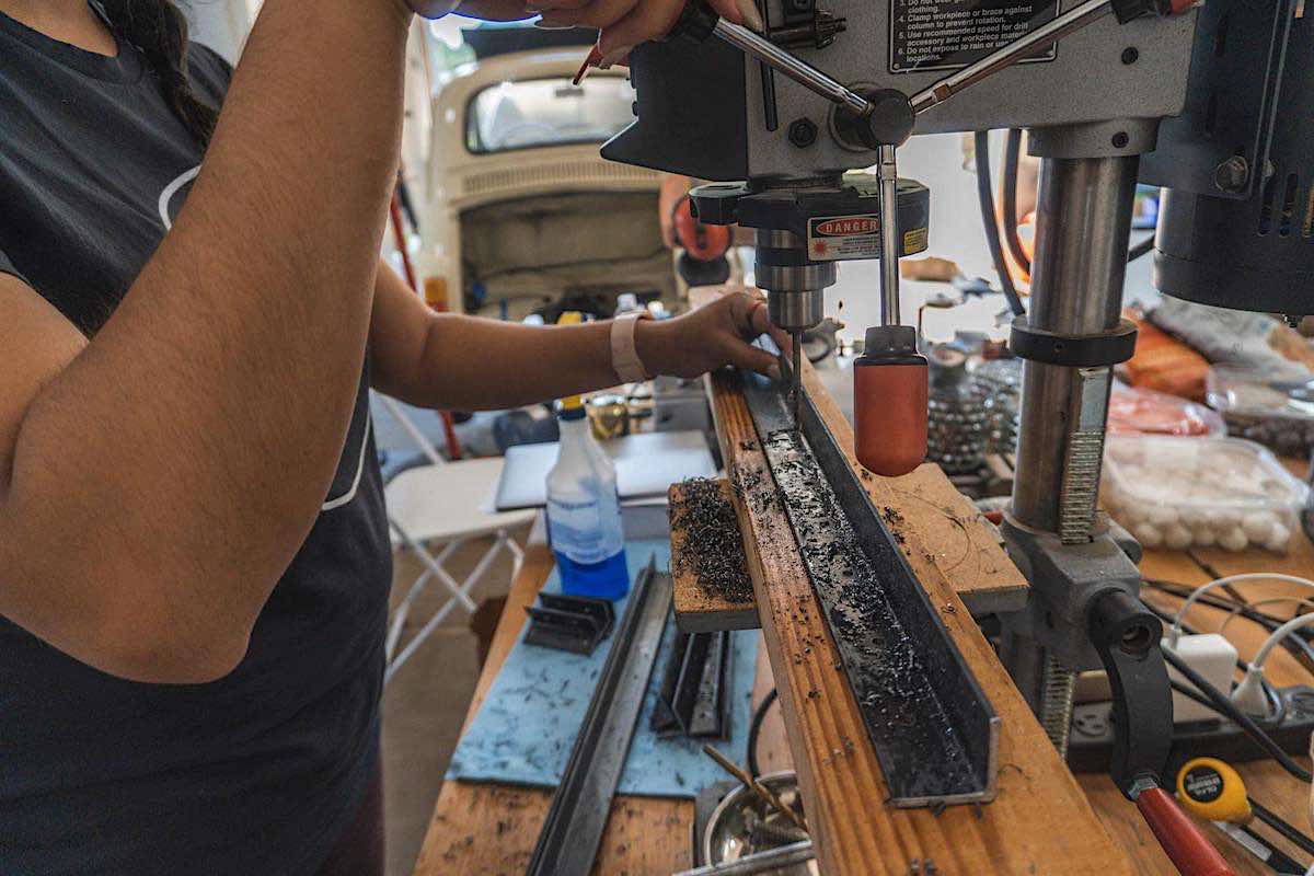
The steel bar made these boxes extremely heavy. The mechanical team decided that this was appropriate because the boxes would be supporting a significant load and contain a high-value part of the car. However, it was still important to be aware of where we used steel, not just for the additional overall weight, but also to maintain safe and efficient weight distribution.
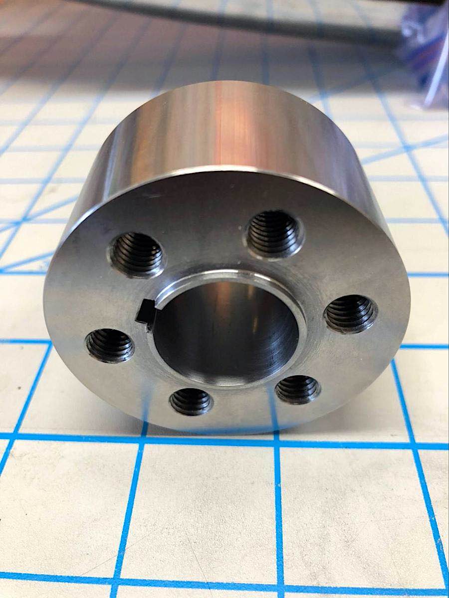
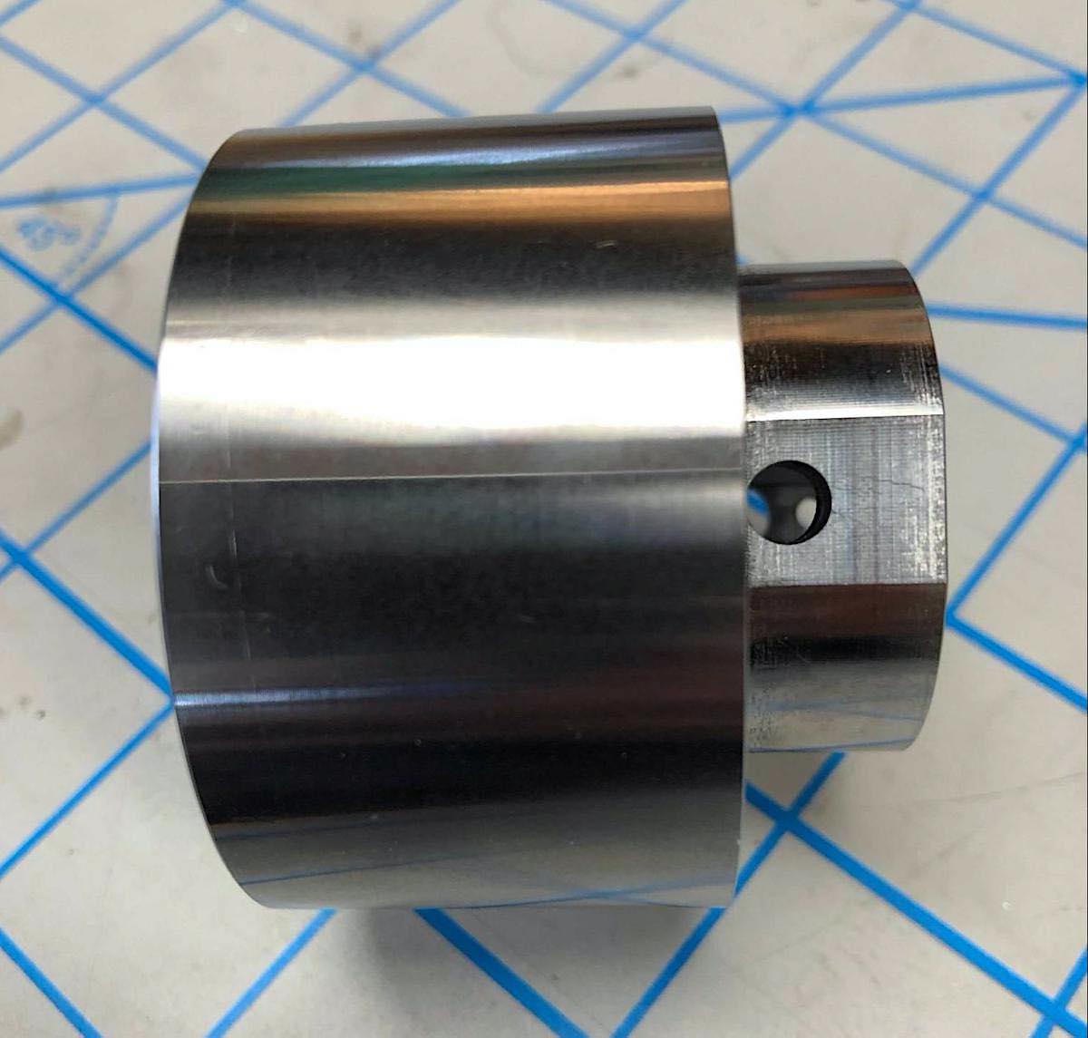
Another important part that we designed was the coupler that fits over the motor shaft and mates with the transaxle shaft. With all of these different parts interfacing, tolerances were critical, so we used ISO 2768 tolerances unless otherwise specified. For the coupler, we used a key from McMaster to fit into a keyway that needed a precise fit, so tighter tolerances were required.
Connecting the motor to the transaxle
Once the components were constructed it was time to tackle mounting them. The inside of Butterball has precious little space structurally capable of serving as a mounting point. Although there’s plenty of sheet metal in the engine bay, it’s not structural and certainly not strong enough to support a 120-pound battery. So, we had to use the actual chassis of the car, which required extra attention to detail. For stability, we used lock nuts where we could and aircraft cable instead of simple wire to hold the battery box in the frunk.
One of our goals in converting this car was to keep everything quiet while driving. One benefit of an electric car is that you don’t have the noisy engine roar, but that means you can also hear every little vibration and rattle everywhere else. To mitigate sounds from internal components, we added foam between the battery boxes and sheet metal of the car and dampeners on the motor.
Overall, we tried to modify the structure of the car as little as possible, so we only removed the original engine, and an exhaust pipe from the trunk area. We avoided messing with the sheet metal so that we could convert the Fiat back to internal combustion if we wanted to.
Lessons Learned
The number one lesson we learned when it came to mechanical design was that designing for assembly is a whole different ball game from modeling. Even though we were able to fit all the components in eventually, we had to get creative with the order of operations to make it work. With a little more planning in the beginning, the assembly process could have been much easier. We made it happen for our one car, but when it comes to assembling things at scale, it’s even more important to carefully consider designing for assembly.
What’s Next
In our other Butterball articles, we discuss the work that went into the electrical system and what we learned about prototyping and building parts yourself versus buying them. A car conversion is a big project, but with a motivated team, we made it work!
Want to learn more about how Fictiv can help with your next project? Create an account and contact us today! Whatever parts you need, we have 3D printing, injection molding, and CNC machining services that unlock your innovation and get you the parts you need.
