Time to read: 7 min
The power of an electronic or mechanical product usually comes from its internal components, but those products are recognizable because of their plastic enclosures. Those outer shells protect the components inside and make the entire system appealing and user-friendly. In this article, we’ll walk you through the steps of designing a prototype plastic enclosure for 3D printing and injection molding.
The enclosure design example we’re using in this article is based on an existing project. The application is for continuous monitoring of the moisture and temperature of indoor vegetation. Inside the enclosure are sensors, a WiFi-enabled Photon developer board, and an online cloud platform called Fathym. For the purposes of this article, we won’t worry about how the enclosure looks. Instead, we’re focusing on functionality.
Step 1: Start with the Product Requirements
When designing a custom enclosure, always start with the application requirements. Generating a problem tree of the mechanical enclosure design will help you understand the specifications and critical design requirements. This method also helps to avoid simple errors and overcomplicated enclosure designs — remember, mistakes made now risk increasing the cost to manufacture the product later on.
So, how do you design an electronic enclosure for monitoring plants? These are our requirements:
- Must house a photon board, a temperature sensor, and a soil moisture sensor.
- Soil moisture sensors must penetrate at least one inch into the soil.
- The two buttons on the top of the board must be accessible when enclosed by the housing.
- The onboard LED must be visible when fully enclosed.
The features listed above define the system requirements, and our plastic enclosure will begin as a simple geometric structure (a box) to enclose the internal system.
The enclosure takes further shape as other considerations develop. For instance, weight reduction should always be considered during product development and a good rule of thumb is to start light and add material as necessary. This consideration specifically targets wall thickness and overall size dimensions.
Pro-Tip: Electronics can generate substantial amounts of heat, so it’s essential to choose an appropriate enclosure material and obtain all electronic component specifications for the system to understand the cooling requirements. Natural or forced conventional cooling systems should be incorporated to avoid overheating.
Step 2: Model the Internal Components
Now that we know the product requirements, it’s time to map out how the internal components will be held and positioned in the enclosure. To do so, you must understand what enclosure components are being used in the system, how they function, and their level of accessibility for operation. In our example, a Photon Particle board, a temperature sensor, and a soil moisture sensor must be contained within the custom plastic enclosure.
By modeling the enclosure’s internal hardware first, we can design the custom enclosure to both secure and protect the Photon board and sensors. Also, it’s critical to create the design with accurately scaled and dimensioned components so that the 3D modeling of the mounting holes and profile of the plastic enclosure are accurate, too.
Pro-tip: Specification sheets, 2D drawings, or 3D models of electronic components are often available from the manufacturer.
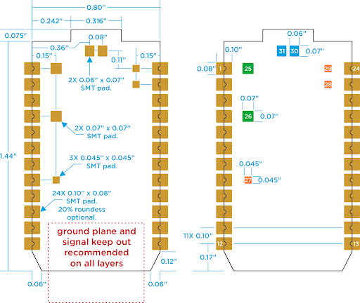
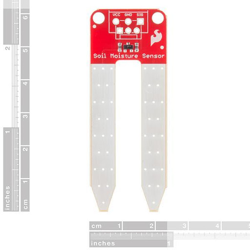
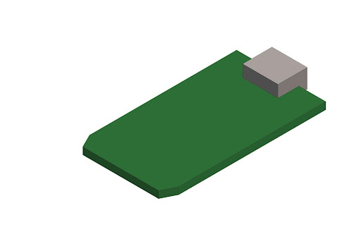
Keep in mind that the placeholder models don’t need to reflect every feature of the part. The critical dimensions are mating features and overall size dimensions, since features that will interact with other parts and dictate mounting should be incorporated into the model.
For instance, the models of the soil moisture sensor and Photon board are pretty blocky, but the extent of the parts is accurately represented below.
Step 3: Create the Shell
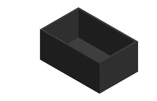
Now that we have models of the enclosure hardware, we can begin designing the plastic box to house them — starting with a rectangular prism to create an open box shape. As you create features, you should strive for uniform wall thicknesses because that’s best practice for injection molding, one of our chosen production methods.
In our example, we’re using .040” wall thicknesses because it works for both 3D printed prototypes and injection molding production.

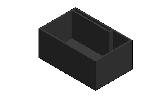
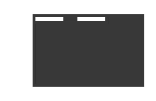
Step 4: Add Slots and External Holes for Soil Moisture Sensor
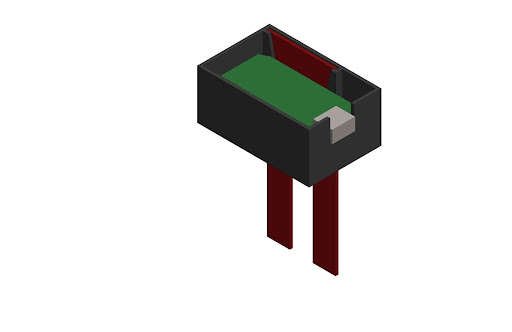
Recall our design requirements? They state that the soil moisture sensor must be inserted at least an inch into the soil. We could run wires from the board to the sensor outside of the enclosure, but fully enclosing the system is the strongest version of the design. So, our enclosure design will have a slot to hold the moisture sensor vertically and allow the probes to pass through the bottom.
Step 5: Create Cutouts for Wire Connections and a Micro-USB Connector
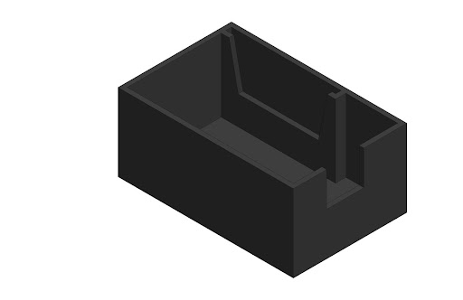
Next, our enclosure needs internal clearance to solder the wires on top of the moisture sensor. We need to remove excess material to create this clearance, while still maintaining the slot where the micro-USB connector will lie. We also need to maintain alignment in this region to the cutout.
Step 6: Create Support Ribs for the Photon Board
The Photon board is currently only held on one side by its micro-USB connector, so we need supports for the board to sit on as well. By adding ribs to the enclosure, we ensure the enclosure not only supports the board, but also adds structural strength to the enclosure itself.
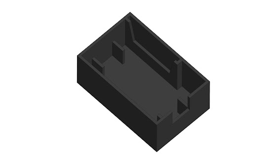
Here’s a current view of the assembly so far.
Step 7: Add Lid Fastener Features
To attach the lid for our enclosure, we need to add features around the outside of the enclosure for the fasteners. In our example, socket head cap screws will be used to attach the lid. So, we’ll add structural through-holes to incorporate the screws into the design. This increases the overall size, since the design prior to this point was only large enough to house the electrical components.
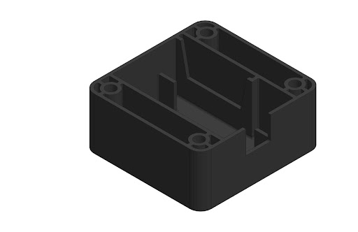
The image above shows the screw bosses that will allow the lid to be attached and the complementary structural ribs that increase rigidity in the attachment locations. All of the geometry has the same uniform thickness of .040”.
Step 8: Add Nut Features
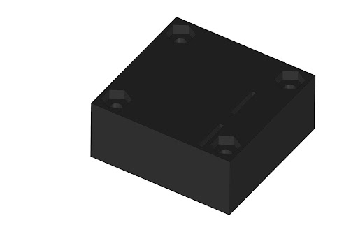
It’s a good practice, when using metal fasteners in plastic parts, to countersink, or cut, the exact size of the nut on the bottom side of the part. This keeps the nut from rotating while you screw in the fastener.
Step 9: Fillet Outer Corners
Next, it’s time to add corner blends to our plastic enclosure. These blends reduce the stress concentration in the corners, add some aesthetic appeal, and reduce the likelihood of tool lock, a potential problem during product assembly.
At the outer corners, the radius (0.140”) will be slightly larger than the inner radius (0.100”). Internal corner radii should also be added to reduce stress locations and avoid fill hesitation. The best practice for adding inner corner and floor radii is to keep the diameter no larger than 10% of the total wall thickness to prevent sink marks during molding. For our enclosure, the ideal floor radii are (0.020”) and (0.022” max).
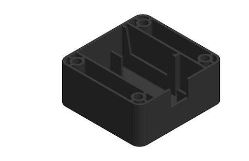
The completed lower section of the mechanical enclosure design is illustrated in the image above, and below is the design with our modeled electrical components.
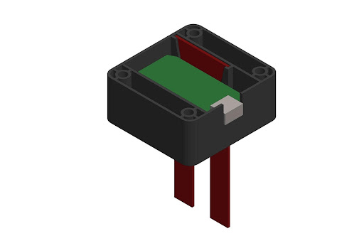
Step 10: Lid Design
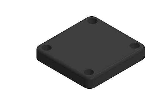
Having completed the lower section of the electrical enclosure, it’s time to design the enclosure lid. The lid will contain the same types of CAD features as the lower section: shelling a box, adding bosses for the fasteners to pass through, countersinking the fasteners, and radiusing the outer corners to match the bottom.
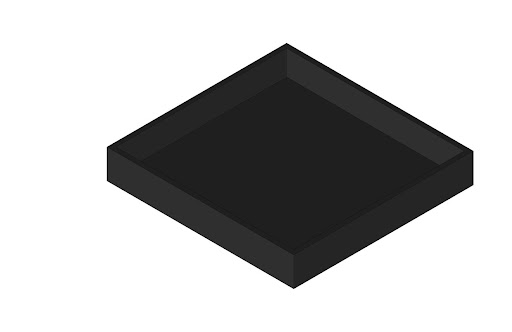
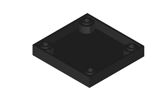
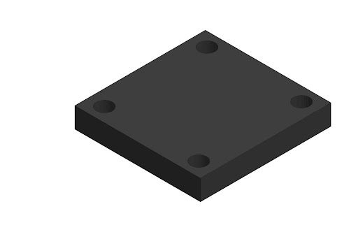
The bosses for the fasteners look as they do above because we are maintaining our uniform wall thickness. Note that the bosses are slightly shorter than the outer wall height so that there are no interferences.
Step 11: Add Protrusion to Hold-Top of Micro-USB Connector
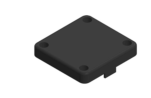
Now we’ll add the boss that will mate with the top of the micro-USB connector and secure it in the slot at the bottom of the enclosure.
Step 12: Add Holes for Buttons and LED Light
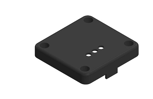
As per the project requirements, next we add holes for the buttons on the board and the LED indicator light.
Step 13: Add Rib for Holding Moisture Sensor
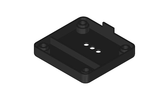
While the moisture sensor is being pushed into the soil, it will probably come in contact with the lid, which we don’t want. So, we’ll add a rib to better secure the moisture sensor.
Step 14: Radius Internal Corners
Our final step is to radius all of those sharp corners with large stress concentrations. Again, we will keep the radii small (.005”) to avoid adding too much material.
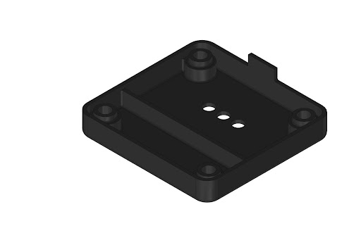
And now our enclosure lid design is complete and ready for full assembly. All electrical hardware can be installed into the lower section of the electrical enclosure and the lid can be set in place and secured.
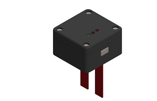
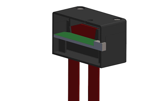
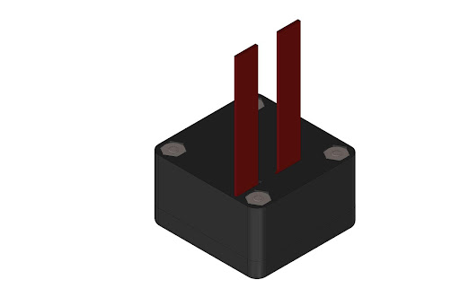
One last note — reserve clearance for the electrical wiring in your design! It’s easy to forget about wire routing while designing the enclosure until it’s time to assemble the fully enclosed electrical box, but electrical wires have minimum bend radii to prevent damaging or kinking the wires. In our example, we provided a half an inch of clearance above the board for wire routing and the temperature sensor.
Additional Enclosure Design Notes
Hopefully, this article will help you design your own plastic enclosures for electronics. For more detail on enclosure design features, check out our posts on how to design snap-fit components, choosing the best fasteners for 3D printed parts, how to conduct a tolerance analysis for 3D printed parts, and how to design light pipes.
There’s a lot to consider when it comes to designing a good plastic electronics enclosure, but making the right decisions leads to lower costs, faster cycle times, and greater part quality. Fictiv is your operating system for custom manufacturing that makes injection molding and 3D printing part procurement faster, easier, and more efficient.
Our injection molding and 3D printing experts can help you to optimize your designs with the design for manufacturing (DFM) assistance you need to make your next plastic enclosure project a success. In the end, Fictiv lets engineers, like you, engineer — instead of sourcing, vetting, onboarding and managing suppliers. To get a quote and get to work, create an account and upload your design today!


