Article contents
▸
Article
Team Fictiv
07.23.2021 DFM Guides
When you upload a part to the Fictiv platform, you receive instant design for manufacturability (DFM) feedback. Here are some explanations for why you received that feedback and what you can do to get your part ready to machine!
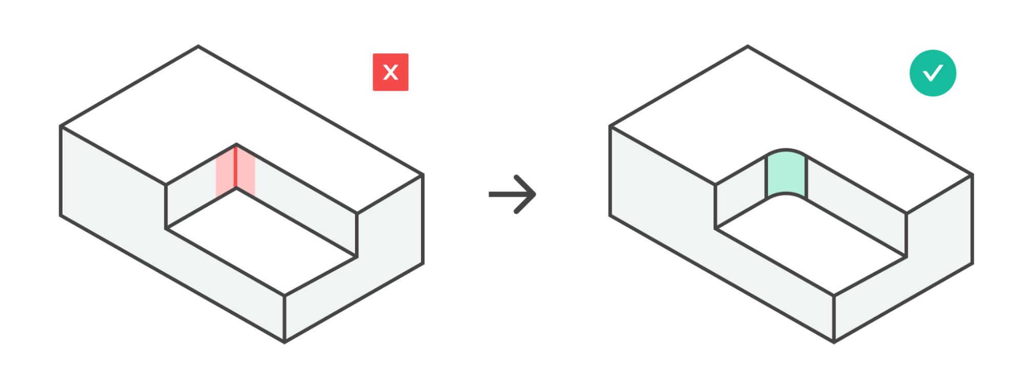
Fillets will be added to sharp internal corners or areas where drafted or sloped edges meet sharp edges. Otherwise, these features are impossible to machine.
If you want to specify radii on your fillets, you can add them to your design. Otherwise, the manufacturer will use their discretion to add fillets to these areas.
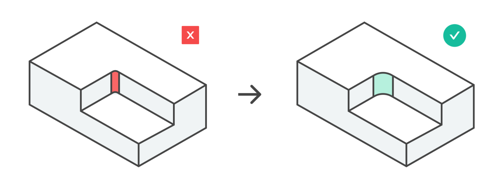
The fillets that are designed into your part are too small to be machined with the smallest end mill that would otherwise be necessary. This adds an extra tool and tool change operation to the CNC machining program, adding time to the overall project.
No action required, unless you want to change the fillets to be a specific size. Otherwise, the machinist will increase the fillet size to avoid using an extra tool.
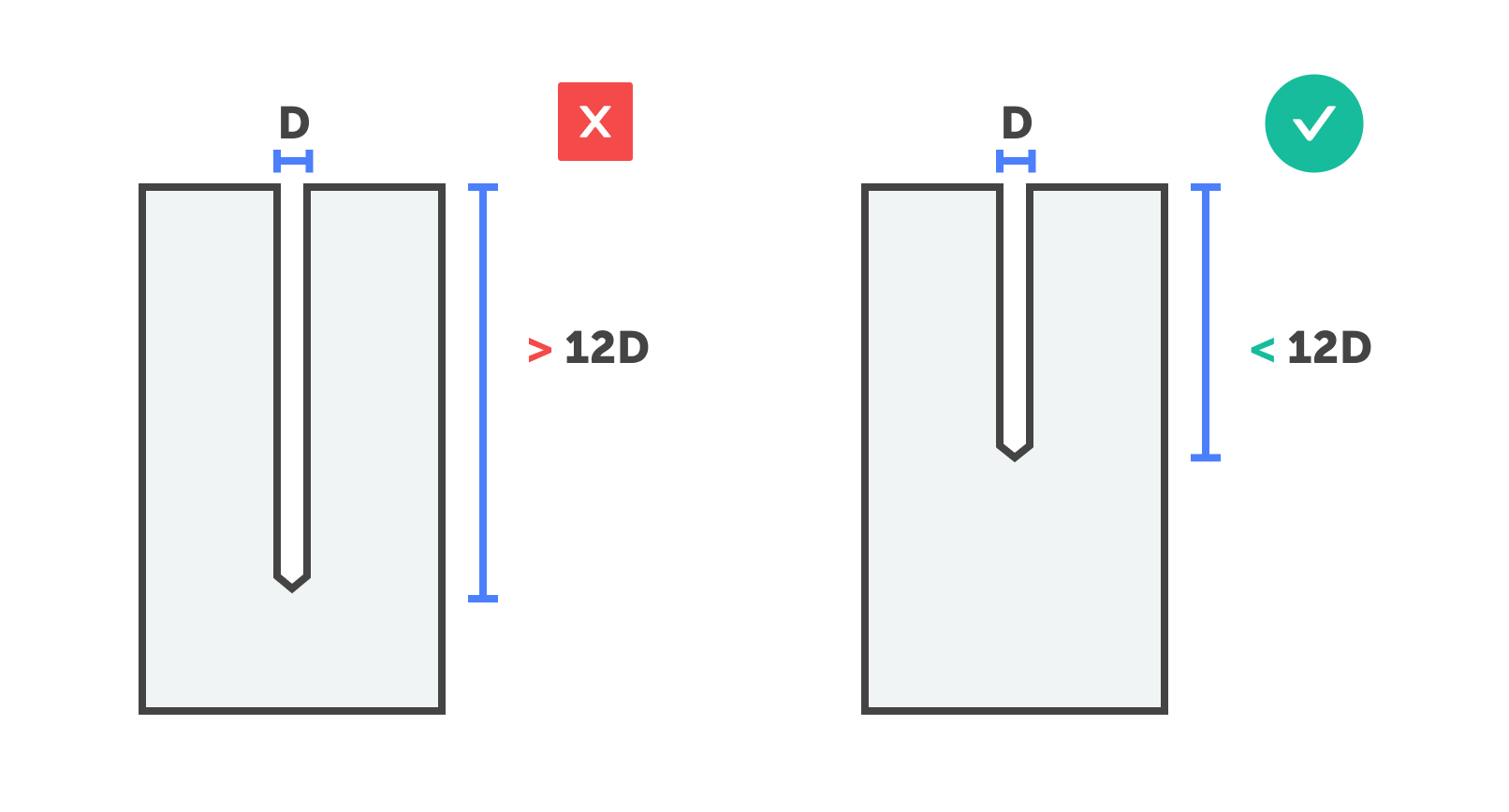
If the depth of a hole in your part is greater than 12x the nearest bit diameter, we will not be able to machine your part. Drills that are greater than 12 times the diameter of the bit are hard to source and may break during drilling. If you increase the diameter of the hole, a larger drill can be used, which would mitigate the issue.
If the hole is a blind hole and is too deep to be drilled, you can try to decrease the depth of the hole or increase the diameter of the hole. The ratio of depth to diameter needs to be less than 12.
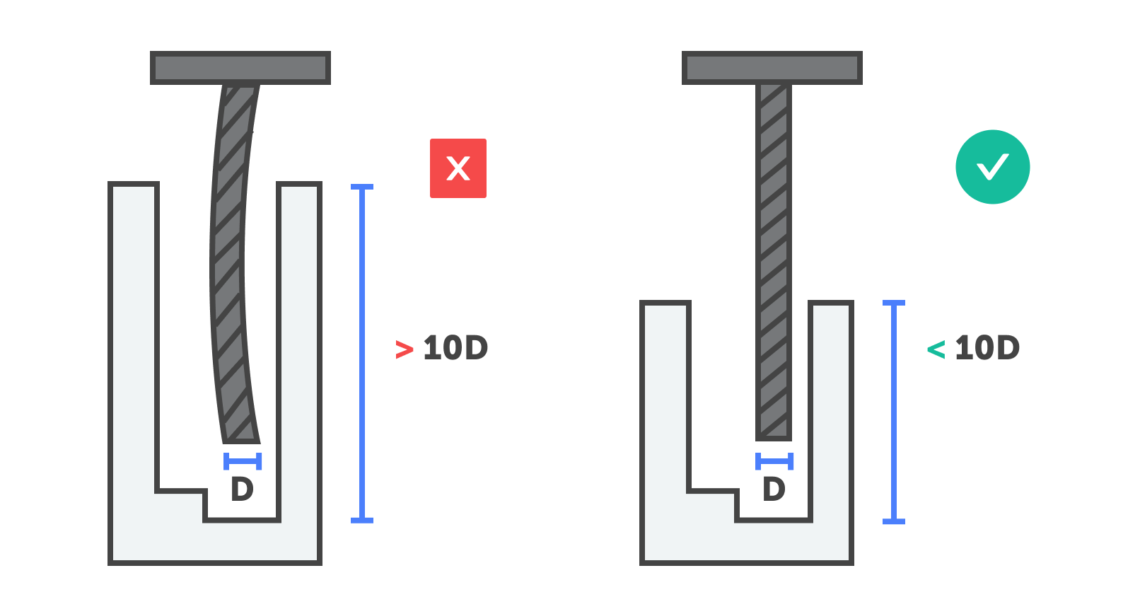
If the depth of a feature in your part is greater than 10x the diameter of the end mill used, we will not be able to machine your part. End mills that are greater than 10 times the diameter of the bit are hard to source and may break during use. This may occur if you have thin but deep features such as slots or grooves.
If you can, decrease the depth of the feature. Otherwise, increase the feature diameter or the corner radius (fillet), which will allow a larger diameter tool to be used. This in turn allows a longer tool.
The fit/function of this thread size cannot be guaranteed because we cannot source a proper thread checker. We can still move forward with manufacturing your part, but it will be a High Risk Product.
In order to guarantee the fit and function of your threads, you can select a standard thread size.
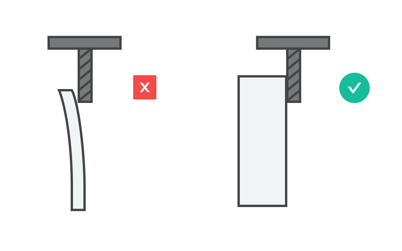
Our minimum required thickness is 0.25mm for metals and 0.50mm for plastics. If the wall is any thinner than this, they will not hold up to the manufacturing process. The material may warp, deform, or break altogether. To move ahead with manufacturing, you will have to update the wall thickness to be above the minimum.
The minimum required thickness is 0.25mm for metals and 0.50mm for plastics. Update your design to be above the minimum thickness of your material.
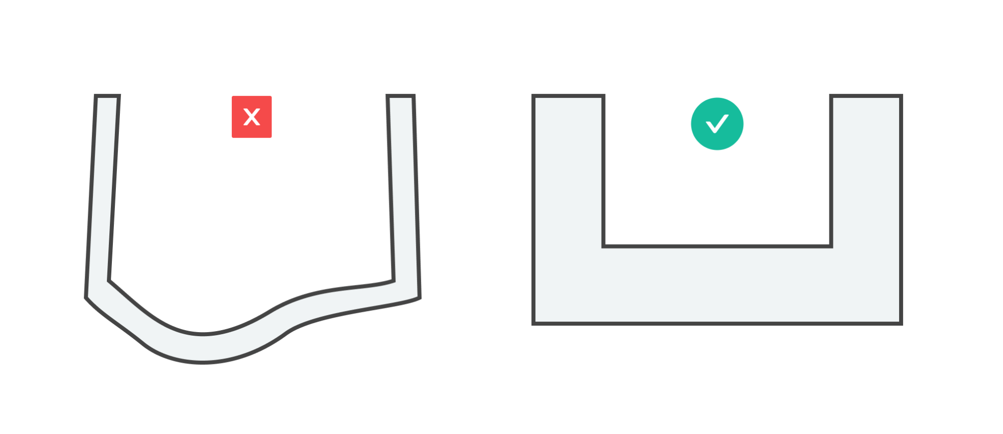
Removing a large amount of material from a part puts a lot of stress on the workpiece, causing warping when the part is removed from the machine.
Evaluate the design of your part (is it best suited to CNC machining?) and the geometry of the final part (thin walls). Add to the wall thickness or consider changing the manufacturing process.
Your part is not optimized for CNC machining. Significant changes must be made for it to be manufactured.
Chat with a Fictiv representative to learn more about why your part failed for CNC machining.
Your part will be manufactured from a specific McMaster part number. This may be stock material that is purchased from McMaster.
You don’t have to do anything, unless you have issues with the part number listed. In that case, contact your Fictiv sales rep.
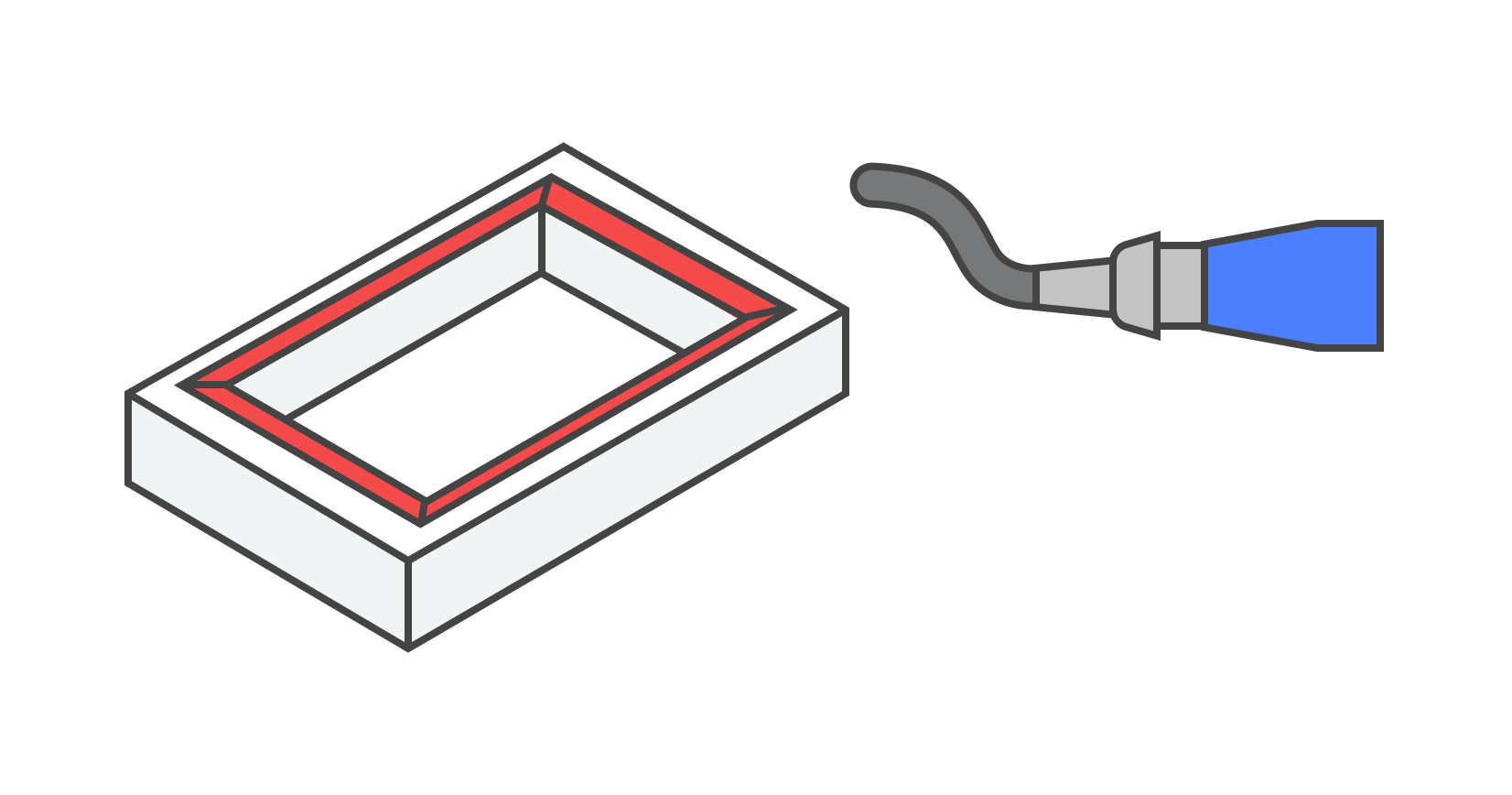
The highlighted areas may be deburred manually due to reachability constraints or the necessary tool geometry required. Some areas may have chamfers that are not accessible with standard tooling. In this case, these areas will be deburred manually.
If you don’t want these features to be deburred manually, you can remove the chamfers from your CAD model.
Due to the part thickness, this part must be made from stock thickness material. However, the thinnest material available is too thick. If we do machine with your desired thickness, the part will end up warped or out of spec.
Reconfigure your part with an alternate material (suggested in your DFM feedback). You can also chat with a Fictiv rep for more recommendations. You can also change the thickness of your design to be the minimum thickness available for your required material.
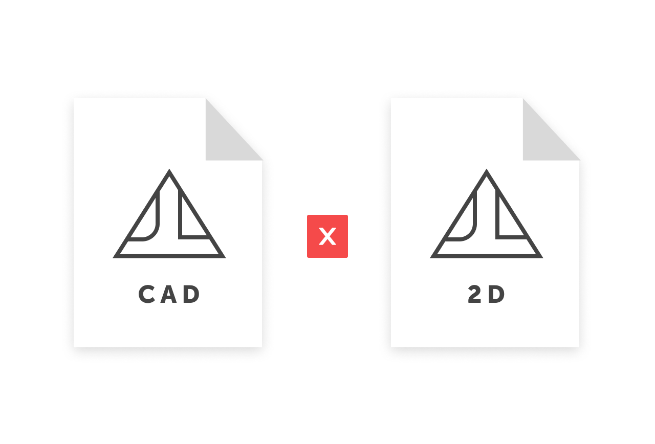
The CAD model does not match the 2D drawing you provided.
If your CAD model is correct and you don’t need a 2D drawing, you can simply remove the 2D drawing. Otherwise, you can upload the correct CAD model that does match the 2D drawing. You can also generate a 2D drawing right on Fictiv’s platform.
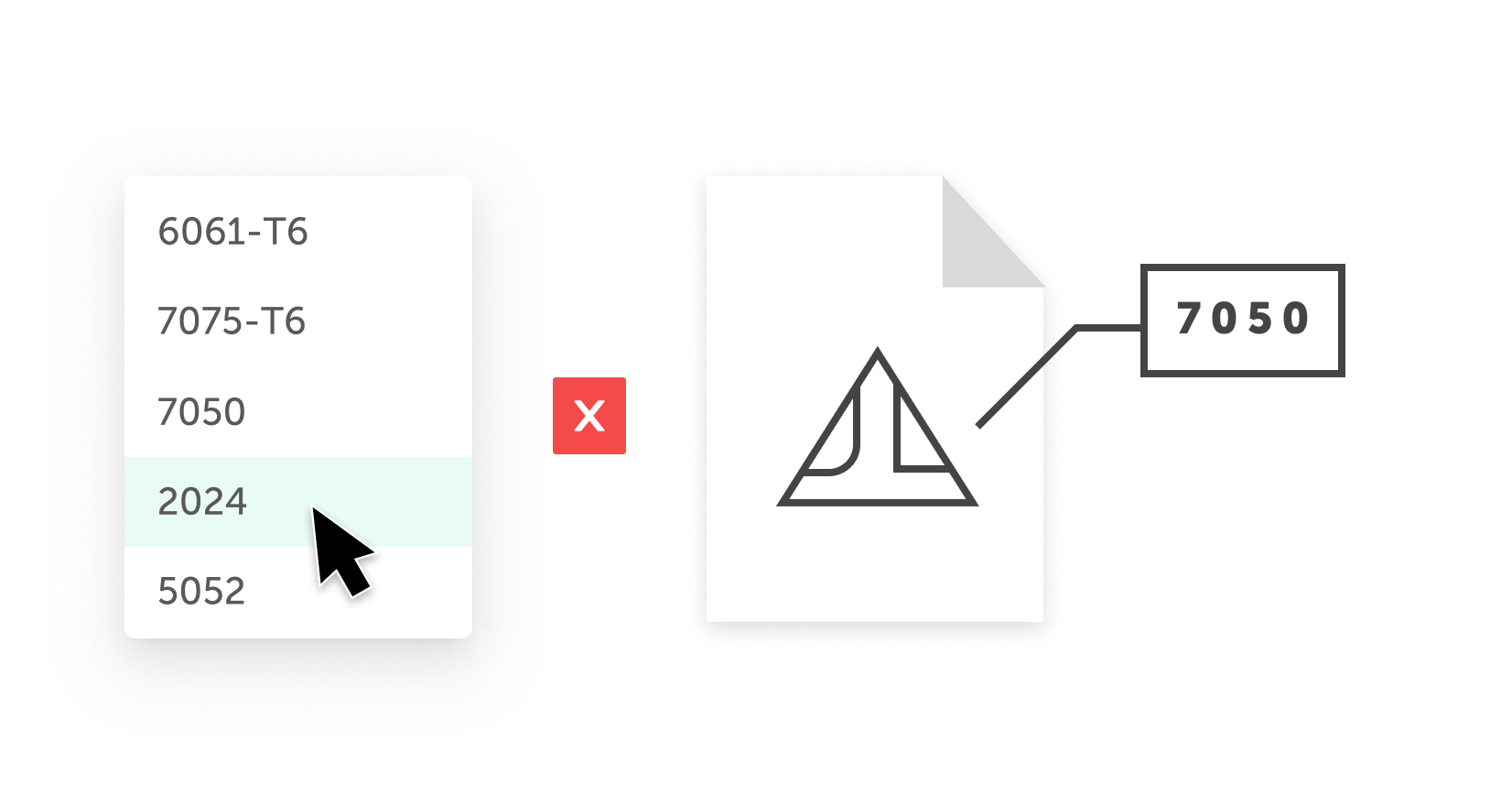
Your material configuration does not match your 2D drawing. We cannot make your parts with this conflicting information.
If your drawing states the correct material, reconfigure your part with the correct material. Otherwise, annotate your drawing to cross out the material and make a note of the correct material.
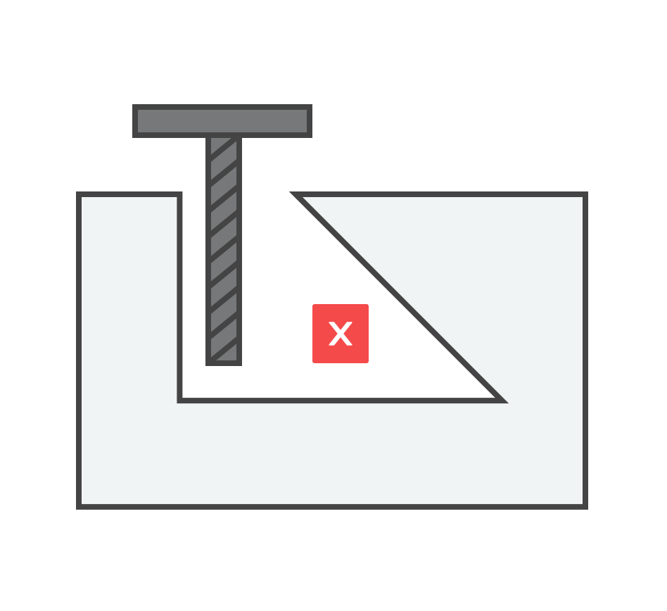
This feature is not fully accessible or machinable with standard tooling. Either it is too deep, at an angle, or obstructed by another feature.
In order to make the feature(s) machineable, please update your model so that the necessary features are reachable. Talk to your Fictiv sales rep for more details.
Due to the design, this feature will be machined with electrical discharge machining, so it is only able to be produced overseas. This may limit the lead time options.
If you require a different lead time or to manufacture domestically, please update your model so that it can be machined using standard tooling.
This feature will be machined using gear hobbing, so it can only be produced overseas. This may limit the lead time options.
If you require a different lead time or to manufacture domestically, please update your model so that it can be machined using standard tooling.
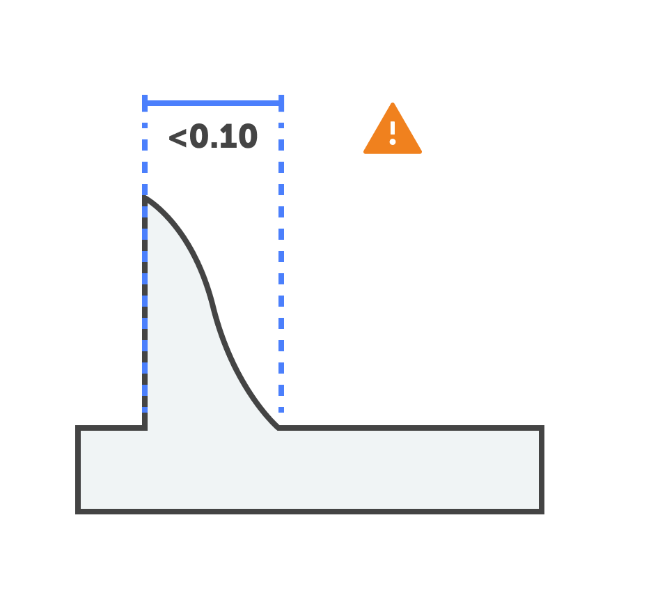
Tight tolerances below a bound of 0.1mm in plastics cannot be guaranteed. Plastic materials can warp due to temperature changes while machining, so we cannot hold tolerances below +/-0.05mm. PEEK has the best dimensional stability with temperature changes and may be a good alternative if your tight tolerances are critical.
If you do nothing, parts will still be machined but we cannot guarantee the tight tolerances. If these tolerances are critical, you can change your material to PEEK.
To learn more about best design for CNC machining, check out Fictiv’s DFM Masterclass!
By signing up, you agree to our Terms of Use and Privacy Policy. We may use the info you submit to contact you and use data from third parties to personalize your experience.
