Time to read: 6 min
Products that are subject to a torsional load often require analysis like the analysis used for bending stiffness. The main differences are the specific material property to be used (Shear Modulus or Modulus of Rigidity) and the polar moment of inertia (which is very similar to the area moment of inertia used in bending). Torsion may be defined as the twisting effect that occurs in a body when a torque, or a twisting force, is applied to it. One example of torsion is the twisting that occurs in a driveshaft when the throttle is applied in a race car.
This article will walk product designers and engineers through the methods used to analyze and improve torsional rigidity in design.
Problem Statement and Target Objectives
This article will review methods to improve a design’s torsional rigidity. Torsional rigidity is the object’s torsional resistance to twisting as a torque is applied to the component and is dependent on a components geometry. As torsional rigidity increases, the torque required to produce a twist of one-unit angular measurement per one unit length of the shaft, increases. In reference to the previous drive shaft example, if the shaft is twisted too much, unstable performance may result, so choosing a shaft with higher torsional rigidity would result in a more stable mechanical interface. The images below show two shafts that each have 100 ft-lbs of torque acting on them, but their deflection will be different because they have different torsional rigidities.
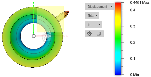
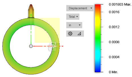
There is a small “flag” modeled on the outside of the shaft to give a visual of the feature twisting as the torque is applied. The design on the left (Steel) is has a higher torsional rigidity and therefore lower stress than the design on right (HDPE). The next section will walk through the properties that make this possible.
Key Properties and Formulas
To improve the torsional rigidity of a design, there are a few material properties to consider. The list below details the key properties:
-
- Shear Modulus, G (modulus of rigidity): a measure of the amount of force required to produce deformation; a higher shear modulus means a material is highly rigid, or a greater force is required to produce deformation
- Polar Moment of Inertia, J: the moment of inertia of the cross-section of an object with respect tothe intersection of the axis and the plane
- Torsional Rigidity = G * J
- Torsional Rigidity may also be related to torque, given the equation:
- Torsional Rigidity= Applied Torque*Length of ShaftAngle of Twist (Radians)
Furthermore, shear modulus, or modulus of rigidity to the modulus of elasticity (E) for isotropic materials can be related, using the following formula:

Where:
- E = Modulus of Elasticity: The rate of normal stress to longitudinal strain; a measure of a material’s stiffness
- v = Poisson’s Ratio: determines how much a material will compress or grow in the direction perpendicular to the direction of the tensile or compressive force on the material
In example, taking the modulus of elasticity of steel at approximately 30e6 psi at room temperature, and converting it to the shear modulus (modulus of rigidity) gives:

The material properties provide a good foundation to determine the torsional rigidity a component. The angle of twist (θ) in radians, where JG is the torsional rigidity, is given by the following equation:
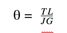
Where:
- T = Torque applied to the component
- L = Length of the component
- J = Polar Moment of Inertia (Torsion Formula Constant)
- G = Shear Modulus (Modulus of Rigidity)
The image below depicts the angle of twist:
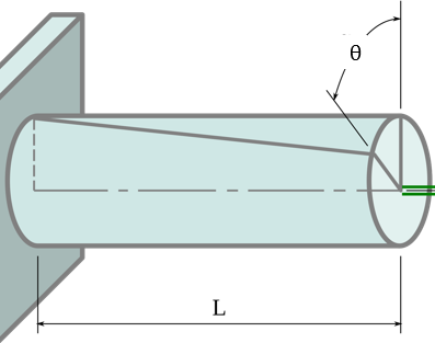
The polar moment of inertia, J, is the same thing as the area moment of inertia about the long axis. That means the formula for determining J will depend on the shape of the component. For a cylindrical shaft, the formula is:

It’s important to remember to use the correct value of J for all calculations, as it can have a big impact on design decisions.
As a reminder, torsional stiffness or torsional rigidity is a measure of the amount of torque required to twist one unit length of an object by one unit radian. The following equation may be utilized to calculate the torsional stiffness (k):
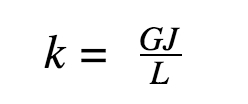
This value may be utilized to compare the torsional rigidity of components directly. From this equation above, the torsional flexibility can also be found by calculating the inverse of k: 1/k.
Applied Example
This section will provide examples of how to solve for polar moment of inertia, shear modulus or modulus of rigidity, stiffness, and angle of twist. The equations will start with a simple solid circular shaft, for simplicity’s sake.
Starting with a shaft that has the following geometry:

Calculating the polar moment of inertia for the defined shaft:

For the purposes of this analysis, the shaft material is aluminum. Aluminum has an elastic modulus of about 10e6 psi and a Poisson’s ratio of 0.33. Calculating the shear modulus or modulus of rigidity gives:

Solving for torsional rigidity or stiffness, gives:

Finally, solving for the radial torsional deflection (angle of twist) with an applied load of 200 in-lb gives:

Changing the material to steel will increase the torsional stiffness by a factor of three. This results one-third of the deflection, or 0.07 rad, for the same applied load. For a situation where the design is very sensitive to positional accuracy, going with a material that has a higher torsional rigidity or stiffness will be beneficial.
If a greater increase in stiffness is needed than can be obtained from a material change alone, increasing the polar moment of inertia will also improve the design. As an example, going from 0.5” to 0.75” brings the polar moment of inertia from 0.00614 in4 all the way up to 0.0311 in4. That means we’re making the part five times as rigid, with only a 50% increase in diameter.
In many instances, part geometries are simply not simple. While the equations for angle of twist, stiffness, and shear modulus (modulus of rigidity) apply, the formula for polar moment of inertia varies with part geometry. As a matter of fact, there may not be a textbook-designed formula for a given geometry. In that event, it’s best to use a CAD system to calculate the polar moment of inertia. This value can be substituted in for J in the remaining equations. The picture below from my previous article on designing for stiffness illustrates how to do this. While the image was captured from CREO, Solidworks can do the same type of analysis.
The highlighted quantities are Area MOI and Polar MOI (J), and as previously discussed, the former is the property of choice for this article. Using a CAD system makes this analysis much easier than hand-deriving a value.
Design Guidelines
Based on these formulas and the overall analytical approach, there are a few important guidelines to remember:
- Increasing a diameter of a circular or near-circular shape (cross-section shape) can have a more significant impact on increasing the torsional stiffness of the component than a material change will.
- The angle of twist increases (directly proportionally) with length, so a reduction in length reduces the total twist the member experiences.
- Young’s modulus may be utilized for a simple estimate of the difference in torsional rigidity if all other properties are held constant. There’s no need to calculate shear modulus (modulus of rigidity) until you’re looking to solve for stiffness or angle of twist.
- A more thorough stress analysis needs to be completed if the loads are expected to induce stresses that numerically approach the material’s torsional strength.
- CAD programs can be very helpful when trying to gather component properties, such as the moment of inertia for a complex shape.
This isn’t an exhaustive list, but it should provide a quick guide to improving the rigidity of any component.
Main Takeaways
Designing for torsional rigidity may sound daunting, but after breaking down the steps, it hopefully feels more manageable. These principles apply to products spanning drive shafts, quadcopters, 3D printers, and much more. For a quick recap, check out these facts:
-
- Torsional rigidity, sometimes referred to as torsional stiffness, is the ability of an object to resist twisting when acted upon by an external force, torque. In mechanics of materials, torsional rigidity is the resistance to angular deformation a material has.
- Torsional Rigidity= Applied Torque*Length of ShaftAngle of Twist (Radians) or
Torsional Rigidity= Shear Modulus*Polar Moment of Inertia
- Torsional rigidity units:
- SI: N*m2
- FPS: lbs
- Torsional flexibility is the inverse of torsional rigidity
- Changing the cross-sectional area of a component will have a bigger impact on its torsional rigidity than a material change.
- Torsional rigidity is the resistance to deflection along an object’s axis of rotation whereas lateral rigidity is the resistance to deflection along an object’s lateral axis.


