Time to read: 8 min
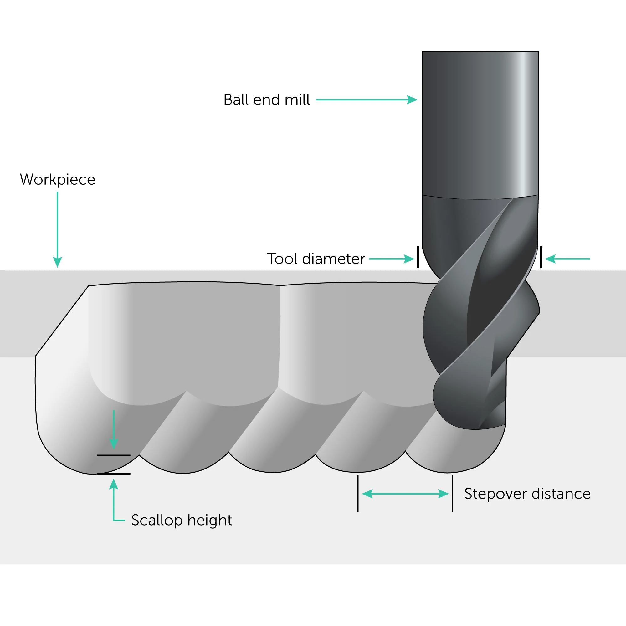
CNC stepover is the distance between successive passes of a cutting tool during computer numerical control (CNC) machining. It’s a critical parameter because it affects both the machining time and surface finish of your parts. Different machining operations need different stepover values, and the optimal value to use also accounts for the tool and the workpiece.

This guide provides an overview of CNC stepovers and explains how to use them with CNC milling, a process that precisely removes material from a raw workpiece to create a part. Other CNC operations, such as turning and grinding, use parameters that are like stepovers but have different names and use different calculations.
What is Stepover in CNC?
In CNC milling operations, the term “stepover” refers to the lateral distance between consecutive tool paths of a cutting implement. Typically, the recommended stepover distance is a percentage of the cutter’s diameter. A machinist can enter the calculated stepover dimension in computer-aided manufacturing (CAM) software or use a CNC stepover calculator in CAM. While an experienced machinist may be able to specify a CNC stepover based on previous projects, there is a simple stepover calculation to use with CNC milled parts.
Calculating Stepover CNC
Stepovers are typically given as a percentage of the tool diameter using the following formula.
Stepover = Tool Diameter x CNC Stepover Percentage
Follow these steps to calculate CNC stepover using some sample data.
1. Determine the cutting tool diameter.
In this example, we’ll use a 10 mm end mill.
2. Set the stepover percentage.
- For roughing, a common range is 40% to 60% of the tool diameter. We’ll use 50%.
- For finishing, the range is usually 5% to 20% instead. We’ll use 10%.
3. Calculate the stepover distance.
- Roughing pass with a 10 mm tool at 50% stepover:
Stepover = 10mm x 0.50 = 5mm
- Finishing pass with a 10mm tool at 10% stepover:
Stepover = 10mm x 0.10 = 1mm
Why are Stepovers Important in CNC Machining?

The stepover parameter affects the surface finish and quality, as well as the total machining time and cost of the part. Depending on what’s most important, some parts may require a smaller or larger stepover.
- Smaller stepovers (5 – 25% of the tool diameter) are used when surface finish is critical. Examples include highly visible parts, precision molds, and many aerospace, medical, and optical components. Keep in mind that while smaller stepovers generally produce a finer surface finish, there is a point of diminishing returns. Extremely small stepovers may increase machining time significantly without a proportional improvement in surface roughness (often quantified as Ra). Therefore, balancing stepover with desired surface roughness is crucial to ensure efficiency.
- Larger stepovers (e.g., 40 – 60% of the tool diameter) are used when machining efficiency is essential or when surface finish is not a critical design feature. Larger stepovers enable quicker material removal. Example applications include large production runs, or when significant amounts of material need to be removed.
Sometimes, a larger stepover is used in what’s known as a roughing pass. A smaller stepover is then used in a finish pass. This is a common practice with parts such as the molds that are used in the automotive industry. This CNC final pass stepover can improve finish quality cost-effectively.
With CNC machining, be sure to keep in mind the distinction between surface finish and surface finishing, which can include additional processes.
Smaller Stepovers
When a stepover is smaller, the distance between successive tool passes is less. This minimizes the height of the peaks and valleys left by the cutting tool, which results in a smoother surface finish. Because each pass of the tool overlaps more closely with the previous pass, there are fewer visible tool marks. Machining takes longer, however, and the speed of material reduction is less.
Smaller stepovers allow cutting tools to capture finer details and more complex part geometries. This is particularly important in finishing operations where the goal is to achieve both high precision and fine surface detail. To develop toolpath algorithms that can accurately and efficiently machine these intricate features, software developers and engineers must consider factors such as tool geometry, material properties, and machine capabilities.
Pros:
- Improved surface finish due to less space between tool passes.
- Better detail capture for complex geometries.
- Even distribution of tool wear across the cutting edge.
Cons:
- Increased tool wear due to the higher number of passes required.
- Longer machining times that can be less efficient, especially for harder materials where cumulative wear can become significant.
Larger Stepovers
Larger stepovers have a greater distance between tool passes. The result is higher peaks and deeper valleys on the part’s surface, or a more noticeable wavy pattern, as larger stepovers also produce a rougher texture with more noticeable tool marks, which can affect the part’s visual and tactile qualities. More material is removed, however, and a larger stepover can be followed by a smaller one to smooth out the surface.
The table below describes the relationship between stepover, surface finish, and machine efficiency. Note the tradeoffs and remember that a larger stepover can be followed by a smaller one.
| Stepover | Surface Finish | Machining Efficiency |
| Smaller | Finer | Less |
| Larger | Rougher | More |
While larger stepovers can reduce overall machining time, they may concentrate wear on a smaller section of the cutting edge. This concentrated wear can shorten tool life, particularly in harder materials or with more aggressive cutting parameters. However, by carefully balancing stepover size with cutting speed and depth of cut, machinists can optimize tool life while maintaining acceptable surface finish and machining efficiency.
What’s the Optimal CNC Stepover?

CNC machinists need to balance surface finish and machine efficiency, but they also need to consider the role of the workpiece material, tool diameter, and tool geometry in stepover selection.
Workpiece Materials
A material’s thermal conductivity and heat resistance play an important role in CNC stepovers.
- Plastics and composites can deform or degrade with excessive heat. By spreading the cutting forces over more passes, however, a smaller stepover reduces the heat generated during machining operations.
- Metals and ceramics can withstand higher temperatures. A larger stepover can be used without adversely affecting the workpiece material. As with plastics and composites, however, different metals have different properties such as hardness and brittleness.
Consider the following:
- Harder materials such as stainless steel and titanium are more difficult to machine and generate higher tool wear and heat. Using a smaller stepover can minimize the load on the cutting tool while achieving a smoother surface finish.
- Softer materials such as aluminum and brass are easier to machine and produce less tool wear and heat. A larger stepover can be used to speed up the machining process without compromising tool life or surface finish significantly.
- Brittle materials such as cast iron and ceramics are prone to chipping and cracking. A smaller stepover reduces the risk of material fracture by lowering the cutting forces on each pass.
- Ductile materials such as copper and plastics deform without cracking. This supports the use of a larger stepover for increased machining efficiency without the loss of an acceptable surface finish.
Beyond stepover adjustments, different materials may also require changes in toolpath strategies, such as altering feed rates or employing specific cooling methods, especially for heat-sensitive materials. For instance, higher feed rates may be necessary for soft materials to avoid excessive heating, while harder materials may benefit from optimized coolant flow to manage the increased heat and tool wear.
Tool Diameter
Tool diameter is an important factor to consider when determining the optimal stepovers because it affects heat, vibration, surface finish, and machining efficiency.
- Larger diameter tools have a larger cutting area, increased rigidity, and better heat dissipation. They support larger stepovers for reduced machining time and may be able to achieve an acceptable surface finish, without the need for a pass over with smaller stepover.
- Small diameter tools use more of the tool’s surface in each cut, which increases heat and vibrations. They need smaller stepovers that remove less material at a time. This reduces machining efficiency, but small diameter tools with small stepovers can support finer finishing.
Tool Geometry
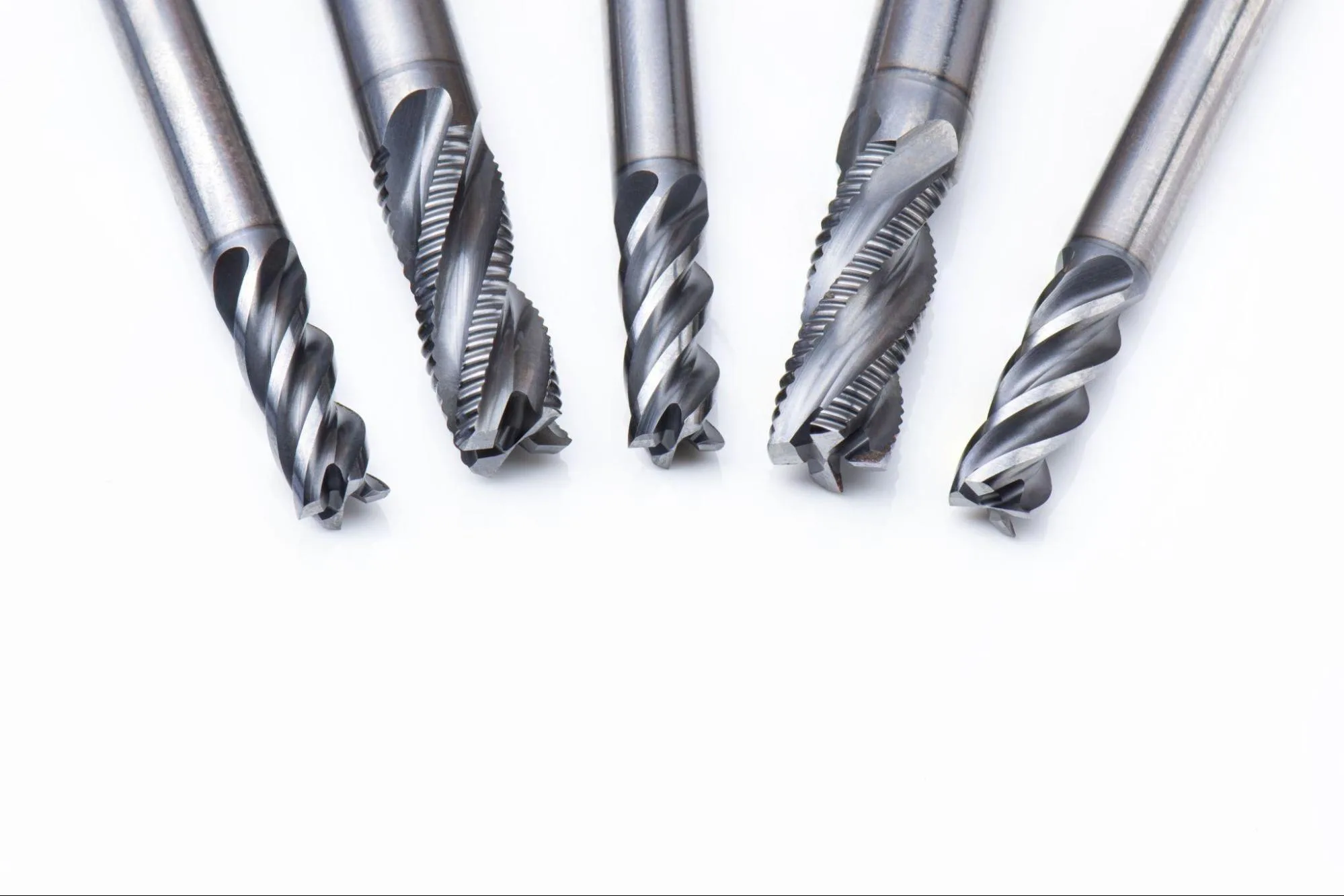
These commonly used end mills show the role of tool geometry in CNC stepovers.
- Flat end mills have a flat cutting surface. They can use a larger stepover for parts with flat surfaces but may need a smaller stepover in the corners of complex parts.
- Ball end mills have a spherical cutting surface for curved and complex parts. A ball end mill needs a smaller stepover because the cutting action occurs over just a part of the tool’s end. Additionally, when working on curved surfaces, the effective cutting diameter changes with the stepover, impacting both surface finish and machining time. It’s crucial to calculate the stepover carefully to avoid excessive scalloping or inefficient machining, especially in finishing operations.
- Bull nose end mills have a flat cutting surface with round corners. They can use a larger stepover on flat surfaces.
Applying a Cutting Tool Stepover for a CNC Machine

Typically, a machinist enters a CNC stepover percentage when using computer-aided manufacturing (CAM) software to generate CNC toolpaths. A designer uses computer-aided design (CAD) software to create a model of the part, and the machinist then imports this model using CAM software such as Mastercam or Autodesk Fusion. The G-code that is generated provides a raster toolpath for the CNC machine.
Based on the CAD model, the CAM software defines the machining operations and generates toolpath offsets. This programmed trajectory defines the movement of the cutting tool in terms of position, machining speed, and direction. Along with feed rate, spindle speed, pass depth, and depth of cut, step over is a key parameter. The tool’s movement can be linear, rapid, or circular. Sometimes, a zigzag toolpath is used instead.
Some stepovers are fixed, but adaptive stepovers are also used.
Adaptive Stepover
Adaptive stepover is a CNC machining strategy that uses toolpath algorithms to dynamically adjust the stepover value based on part geometry and the cutting conditions. Typically, it’s used with complex and variable parts where a fixed stepover would be inefficient. The advantages of adaptive stepovers include consistent cutting loads, optimal material removal, improved tool life, and a better surface finish.
Adaptive stepovers are particularly advantageous when dealing with irregular geometries or variable material thicknesses, where a fixed stepover might lead to excessive tool engagement or uneven material removal. By adjusting the stepover dynamically, the cutting forces remain consistent, reducing the risk of tool breakage, and ensuring a uniform surface finish. This strategy also helps in maintaining efficient machining speeds while minimizing tool wear, making it ideal for high-precision or high-complexity parts.
CNC Milling Stepover vs. Stepover in Other CNC Operations
Stepover is a term that’s associated with CNC milling, but other CNC processes have related concepts. For example, with CNC turning, the equivalent concept is the depth of cut. This refers to the thickness of the material layer that’s removed in a single pass. In CNC drilling, the concept that’s closest to stepover is pecking depth, where the tool retracts to clear chips between drilling cycles. Among non-milling CNC processes, CNC router stepover is the most similar to milling.
Choose Fictiv for CNC Machining Services
Fictiv provides CNC machining services that can help you accelerate prototyping, product development, and production. To apply the proper CNC setup to your parts, our manufacturing partners balance machining efficiency vs. surface finish and carefully consider the role of workpiece material, tool geometry, and tool diameter.
Importantly, Fictiv is committed to both quality and efficiency. Our globally vetted network is powered by our ISO 9001 quality certification and manufacturing partners certified to AS 9001, ISO 13485, and ISO 16949. Design Engineers and Supply Chain Professionals also like how parts can be delivered in as quickly as 2 days, and how 95.4% of orders are delivered to your specifications and on time. For complex CNC machined parts delivered at ridiculous speeds, Fictiv is the smart choice.
Create a free account and upload your CAD file to get started.


