Time to read: 11 min
Like most SOLIDWORKS software users, you likely collaborate with other people on part designs or assembly projects. Collaboration is typically a good thing. After all, two heads are better than one, right? However, not everyone uses SOLIDWORKS, so the people you collaborate with likely end up sending you files with extensions like IGES, QIF, JT, STL, STEP, X_T, etc.
The last thing you want to happen is to encounter a SOLIDWORKS imported geometry error or other import errors when trying to work on a project with a team. Seeing these errors pop up is extremely frustrating and they can be complex to resolve. This has been a recurring theme throughout my career and is one of the most frustrating things that rears its ugly head again and again.
Here are a few best practices for fixing SOLIDWORKS import errors, so you can spend more time designing and a lot less time fixing errors.
Guidelines for Dealing with Import Errors in SOLIDWORKS
The best practices discussed in this article are broken up into a quick & dirty strategy, as well as a much more thorough, deep-dive strategy. My recommendation (and what I personally do) is to start with the quick & dirty approach and escalate to the deep-dive approach if needed.
The reasons for SOLIDWORKS imported geometry errors may stem from one of the following reasons:
- Bad surface geometry
- Bad surface topology (i.e. trim curves)
- Adjacent surfaces have edges that are close to each other but do not meet; this results in a gap between those adjacent surfaces
Note: The content discussed from here on out is highly technical and uses a lot of jargon. If you aren’t familiar with a command that I discuss, please refer to the glossary at the end of the article for more information. If you need more information about how a command works, search for the command in the SOLIDWORKS database. You can even drag and drop useful commands into the toolbar for simplified future use.
Quick & Dirty Strategy
1. The Magical “Attempt to Heal All” Button: Import Diagnostics
SOLIDWORKS has a useful, built-in Import Diagnostics wizard that will attempt to assess and/or repair imported geometry errors. Specifically, the Import Diagnostics wizard is good at repairing faulty surfaces, knitting repaired surfaces into closed bodies, and making closed bodies into solids.
The tool is quite powerful and should not be overlooked. If a model is imported with faults, an error message should pop up and ask if you want to run Import Diagnostics – click Yes to begin. If the wizard does not pop up automatically when you import geometry, you can open the wizard by clicking: Tools > Evaluate > Import Diagnostics. The icon looks like this:
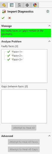
![]() The wizard will list all “faulty faces” (they are exactly what they sound like) and “gaps between faces”, which are basically missing surfaces or holes in your model. Once open, the wizard may look like this:
The wizard will list all “faulty faces” (they are exactly what they sound like) and “gaps between faces”, which are basically missing surfaces or holes in your model. Once open, the wizard may look like this:

Note: If you are intentionally importing a surface body (a body that is not completely enclosed and therefore “solid”, the surface’s boundary will come up as a “gap”. In that case, you can ignore that gap.
The wizard finds problems by running the Evaluate > Check function and searching for additional errors, such as overlapping surfaces, non-simplified surface (B-splines that are planar), etc.
Once this wizard lists all the errors, it gives you the option to “Attempt to Heal All”, “Attempt to Heal All Faces”, or “Attempt to Heal All Gaps”. The Import Diagnostics feature works to fix errors when importing to SOLIDWORKS by performing one of the following:
- The wizard works to repair errors in geometry, the underlying surface, and topology, the boundaries, of faces by recreating the trim boundaries of a face (to fix overlap), trimming defective portions of faces, or removing the face and utilizing a gap repair algorithm to fill the resulting hole.
- The wizard works to fix gaps between adjacent faces by swapping two close, but non-intersecting edges, with a single edge, filling the gap with a created fill or lofted surface, or merging two adjacent faces to fill a gap.
2. Decide for Yourself if You Can Ignore the Errors
If you have tried out the Import Diagnostics wizard and have not had success, you should ask yourself: “What am I going to do with this CAD model?” or “What are the requirements for the goals I hope to accomplish by importing this CAD model?”. If you are importing a part to simply simulate it or take measurements from it, don’t waste your time trying to fix it. You can also simply put a CAD model into an assembly and overlay it against other parts for comparisons, etc., without ever fixing the import errors. However, if you will ever be making design changes to that CAD model, OR you are using the CAD model as-is for 3D printing or cutting molds, you should fix those errors right away!
3. Try to Have the File Re-Sent to You in Another Format
Import errors are often caused by translating the content of a file from one 3D modeling program’s behind-the-scenes coding language to another’s. Some of these programming languages translate more accurately between each other than they do with others. The same is true with human languages, as well. It might be easier, for example, to translate a Spanish phrase or joke into Italian, instead of into Russian, because those languages have similar roots. In this case, Spanish and Italian are Romance languages, while Russian is a Slavic language. In SOLIDWORKS, the errors when trying to import a file with another root programming language may show up as a SOLIDWORKS import step file error or SOLIDWORKS rebuild error on import.
Considering the above, consider asking the person who sent you the file to resend you a file type that is more compatible with SOLIDWORKS. The same geometry imported through a different file type may import into SOLIDWORKS with no errors at all, OR with errors that are easily fixed with the Import Diagnostics wizard.
Per Dassault Systemes (SOLIDWORKS parent company), ICES, STEP and STL files import the best into SOLIDWORKS. IGES is perhaps the most universal 3D file type. It was created in the late 70’s (you read that right) and is shared by almost all 3D modeling programs created since then. In my personal experience, however, IGES files tend to produce the most errors. So, despite the widespread use of IGES files, I try to avoid importing them whenever possible. STEP files have also gained popularity so they are another excellent choice.
4. Can Someone Else Do This for You?
The next thing you should ask yourself is, “Can someone else do this for me?” Consider asking an intern to do the error-fixing work for you, so you can maximize the utility of your time and provide valuable experience for the intern. In my opinion, one of the best ways to become a SOLIDWORKS surface modeling pro is to spend time fixing surface errors.
For other tips & tricks for becoming a SOLIDWORKS pro, read 4 Tips & Tricks to Become a SOLIDWORKS Pro.
Deep-Dive Strategy
If you’ve tried all the steps in the quick & dirty strategy for fixing SOLIDWORKS import errors, and you’re still seeing errors on your screen, it’s time to dig deep to clean up your CAD model. Keep your head high and try the following methods to fix your part:
1) If Your Part is Symmetric, Cut Your Part in Half BEFORE Trying to Fix Errors
Why do twice the work when you could do half instead?
- If your part shows up as a surface, use the Trim Surface command
![trim surface command icon]() (Insert > Surface > Trim) to cut it in half using the symmetry plane.
(Insert > Surface > Trim) to cut it in half using the symmetry plane. - If your part shows up as a solid, use the Cut with Surface command
![cut with surface command icon]() (Insert > Cut > with Surface) to cut it in half using the symmetry plane.
(Insert > Cut > with Surface) to cut it in half using the symmetry plane.
In some cases, the error within the file is serious enough that SOLIDWORKS will not let you cut the part in half. This can be super frustrating. Here are some strategies that you should try, in my personal order of preference:
Method #1 for cutting your part in half (if the cut function doesn’t work):
- Create a new Reference Plane that is slightly offset from the correct symmetry plane. Use the new Reference Plane to trim your error-filled surface or cut your error-filled solid nearly in half, making sure that you keep the slightly bigger side. Good enough to start.
- Delete every face on one side of the part. For any face that crosses the symmetry plane, either don’t delete it at all (consider where you are to be good enough) OR apply the Split Line command to split it on the symmetry plane. Then, delete the half of the split face that you don’t want.
- Offset every error-free face on one side of the part by 0mm and then use the Delete Body command on the original solid or surface.
Although offsetting half of the model achieves the same result as deleting half of your model, this method is much less ideal because it is much less likely to work. When you are offsetting faces, if you miss certain faces OR pick a face that contains a hidden error, the command might not even complete. This method is the last resort for cutting your model in half and takes the most amount of time to successfully complete.
Method #2 for cutting your part in half (if the cut function doesn’t work):
This method is by far my most commonly used, based on practical experience (Pay attention to the following, little-known tip).
In many cases, you will try to use the Delete Face command
![]() (Insert > Face > Delete) with the option set to “delete”, and the command itself won’t work on your model. In fact, it won’t let you delete ANY of your model’s faces. Not even one! That’s crazy!
(Insert > Face > Delete) with the option set to “delete”, and the command itself won’t work on your model. In fact, it won’t let you delete ANY of your model’s faces. Not even one! That’s crazy!
Here is the workaround:
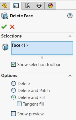
Use the Delete Face command
![]() (Insert > Face > Delete), with the option set to “Delete and Fill”, as shown below. Now, choose a single face from your model at random. Nine times out of ten, the command will work, and it will replace that face with some weirdly shaped surface. Ignore the new surface. Now, try the Delete Face command again, on whatever face you want, using the “Delete” option. Now, it will allow you to delete the face(s) SOLIDWORKS wouldn’t let you delete before. Does this make any sense? Of course not, but this method does work on some versions of SOLIDWORKS. Try it out for yourself and see if this workaround works for you!
(Insert > Face > Delete), with the option set to “Delete and Fill”, as shown below. Now, choose a single face from your model at random. Nine times out of ten, the command will work, and it will replace that face with some weirdly shaped surface. Ignore the new surface. Now, try the Delete Face command again, on whatever face you want, using the “Delete” option. Now, it will allow you to delete the face(s) SOLIDWORKS wouldn’t let you delete before. Does this make any sense? Of course not, but this method does work on some versions of SOLIDWORKS. Try it out for yourself and see if this workaround works for you!
2) Rerun the Import Diagnostics Wizard on Half the Model
As mentioned at the beginning of this article, the Import Diagnostics wizard is an excellent tool for fixing import errors. However, the Import Diagnostics wizard will only work on NEWLY imported geometry. Once you add commands to the feature tree, the Import Diagnostics wizard will grey itself out and become unavailable. If you have made changes to your part (including cutting or trimming your part in half) and would like to re-run the Import Diagnostics Wizard, save your updated part as a parasolid (*.X_T), or another equivalent file type, and then delete all the features in your feature tree, OR start a new SOLIDWORKS part file. Now, import the Parasolid, or other model, you created.
Note: You can import Parasolid files into an already open SOLIDWORKS part by using Insert > Feature > Imported.
Since the newly imported geometry will be the only feature in your feature tree, the Import Diagnostics wizard will be available to you again. So, re-run the Import Diagnostics wizard and use the “Attempt to Heal All” button (See the The Magical “Attempt to Heal All” Button: Import Diagnostics section above).
3) Delete any Remaining Problematic Faces and Fill them Back in
If you are still getting a few faces that are showing up with errors, delete them. They’re not worth it. You can fill them in using a variety of tools, such as Filled Surface
![]() (Insert > Surface > Fill), Surface Loft
(Insert > Surface > Fill), Surface Loft
![]() (Insert > Surface > Loft), and Boundary Surface
(Insert > Surface > Loft), and Boundary Surface
![]() (Insert > Surface > Boundary Surface). Having a surface that is off by 0.005mm is still better than one that has a geometry error in it that will keep giving you headaches down the line.
(Insert > Surface > Boundary Surface). Having a surface that is off by 0.005mm is still better than one that has a geometry error in it that will keep giving you headaches down the line.
Notes:
- If you’re already in the Import Diagnostics wizard, you can right-click on the problematic face within the list of problematic faces and choose “Delete”.
- Otherwise, you can use the Delete Face command
![delete face command icon]() (Insert > Face > Delete), with the option set to “Delete”.
(Insert > Face > Delete), with the option set to “Delete”.
4) Save Your File as a Different File Type and Then Re-Import it
This should be your absolute last resort. I cannot stress that enough. When I encounter a geometry error that simply won’t go away, no matter what I do, one of my last options is to save that geometry as an IGES file and try importing it again. I already explained that IGES files tend to not translate well into SOLIDWORKS. In this case, you’re hoping for a translation mistake from SOLIDWORKS into IGES and/or from IGES back into SOLIDWORKS. You’re hoping that a translation mistake could end up being a good thing. How? You’re hoping that the new set of faulty faces and/or gaps are more easily fixed by the Import Diagnostics wizard than the original errors were, to begin with. This sounds crazy, and it is. That’s why this is the last resort. Believe it or not, this does sometimes work. Thankfully, I rarely must try it out.
Summing Things Up
We’d all like to spend more time designing and less time fixing errors. This article provides several strategies for fixing import errors in SOLIDWORKS that may arise when importing non-native files. Remember to use the Import Diagnostics wizard to your advantage with complex problems resolved ideally on only half of your symmetrical model. Also, don’t forget that you can use the Import Diagnostics wizard, even after you have manipulated a CAD model, if you follow the proper steps. Now that you know the best practices for dealing with import errors, share what you’ve learned with your friends, and try the best practices out yourself. And don’t forget, as Dale Carnegie once said, “Knowledge isn’t power until it is applied.”
Glossary of SOLIDWORKS Commands
- To create a new Reference Plane, use the Plane command
![plane command icon]() (Insert > Reference Geometry > Plane)
(Insert > Reference Geometry > Plane) - To trim a surface with a Plane, use the Surface Trim command
![trim surface command icon]() (Insert > Surface > Trim)
(Insert > Surface > Trim) - To cut a solid using a Plane, use the Cut with Surface command
![cut with surface command icon]() (Insert > Cut > with Surface)
(Insert > Cut > with Surface) - To offset faces of a surface or solid, use the Surface Offset command
![]() (Insert > Surface > Offset) and set the offset distance to 0
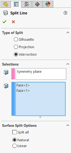
(Insert > Surface > Offset) and set the offset distance to 0 - To split a face using a plane, use the Split Line command
![]() (Insert > Curve > Split Line) and choose the option for Intersection
(Insert > Curve > Split Line) and choose the option for Intersection
- To delete an entire surface or solid, use the Delete/Keep Bodies command
![]() (Insert > Features > Delete/Keep Body)
(Insert > Features > Delete/Keep Body) - To delete faces of a surface or solid without filling in the resulting hole, use the Delete Face command
![delete face command icon]() (Insert > Face > Delete) and set the option to “Delete”
(Insert > Face > Delete) and set the option to “Delete”
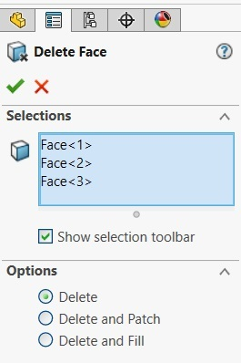
- To delete faces of a surface or solid and automatically fill in the deleted face(s), use the Delete Face command
![delete face command icon]() (Insert > Face > Delete), and set the option to “Delete and Fill”
(Insert > Face > Delete), and set the option to “Delete and Fill”
